Exhaust gas purification device

Inactive Publication Date: 2015-01-06
YANMAR POWER TECHNOLOGY CO LTD
View PDF23 Cites 6 Cited by
  • Summary
  • Abstract
  • Description
  • Claims
  • Application Information

AI Technical Summary

Benefits of technology

[0023]According to the first aspect of the present invention, in the exhaust gas purification device which is provided with the gas purifying body which purifies the exhaust gas discharged by an engine, and the gas purifying housing which is provided with the gas purifying body therein, the exhaust gas purification device is provided with the support bracket which supports the gas purifying housing, the bolt hole is formed in the support bracket, the insertion guide is formed in the support bracket, and the attaching bolt is engaged with and disengaged from the bolt hole via the insertion guide. Accordingly, after installing the attaching bolt for the temporally fixing to the attaching position in the engine side or the main machine side to which the support bracket is connected in a pre-set state, the bolt hole can be engaged with the attaching bolt via the insertion guide, and the gas purifying housing can be supported to the attaching position. In other words, the worker can fasten the attaching bolt for an after attaching so as to fasten the support bracket in a state of releasing hands from the gas purifying housing. It is possible to carry out an attaching and detaching work of the gas purifying housing by one worker. It is possible to improve an assembling workability of the gas purifying housing which is a heavy load.
[0024]According to the second aspect of the present invention, the insertion guide is formed by the bolt inserting notch which is provided in the support bracket, the bolt hole is left open to the side edge of the support bracket via the bolt inserting notch, the bolt hole is engaged with the attaching bolt in the temporally fixed state via the bolt inserting notch, and the gas purifying housing is structured such as to be supportable via the attaching bolt in the temporally fixed state. Accordingly, it is possible to engage the bolt hole with the attaching bolt which is temporarily fixed in the pre-set state via the bolt inserting notch. In other words, the worker can fasten the attaching bolt for an after attaching so as to fasten the support bracket in a state of releasing hands from the gas purifying housing. It is possible to carry out an attaching and detaching work of the gas purifying housing by one worker. It is possible to improve an assembling workability of the gas purifying housing which is a heavy load.
[0025]According to the third aspect of the present invention, the outside case body is fitted to the outer side of the exhaust gas purifying case which is provided with the gas purifying body therein, the gas purifying housing is formed by the exhaust gas purifying case and the outside case body, and the support bracket is firmly fixed to the outside case body integrally. Accordingly, it is possible to easily achieve a thermal insulation of the exhaust gas purifying case and an improvement of a rigidity of the gas purifying housing, by the outside case body.
[0026]According to the fourth aspect of th

Problems solved by technology

Therefore, there is such a problem that it is impossible to reduce an assembling man hour of the DPF.
On the other hand, one worker can fasten the attaching bolt so as to fix the DPF to the engine or the machine body side by lifting up the DPF by utilizing a lifting machine such as a chain block or the lik

Method used


Image

  • Exhaust gas purification device
  • Exhaust gas purification device
  • Exhaust gas purification device

Examples


Example

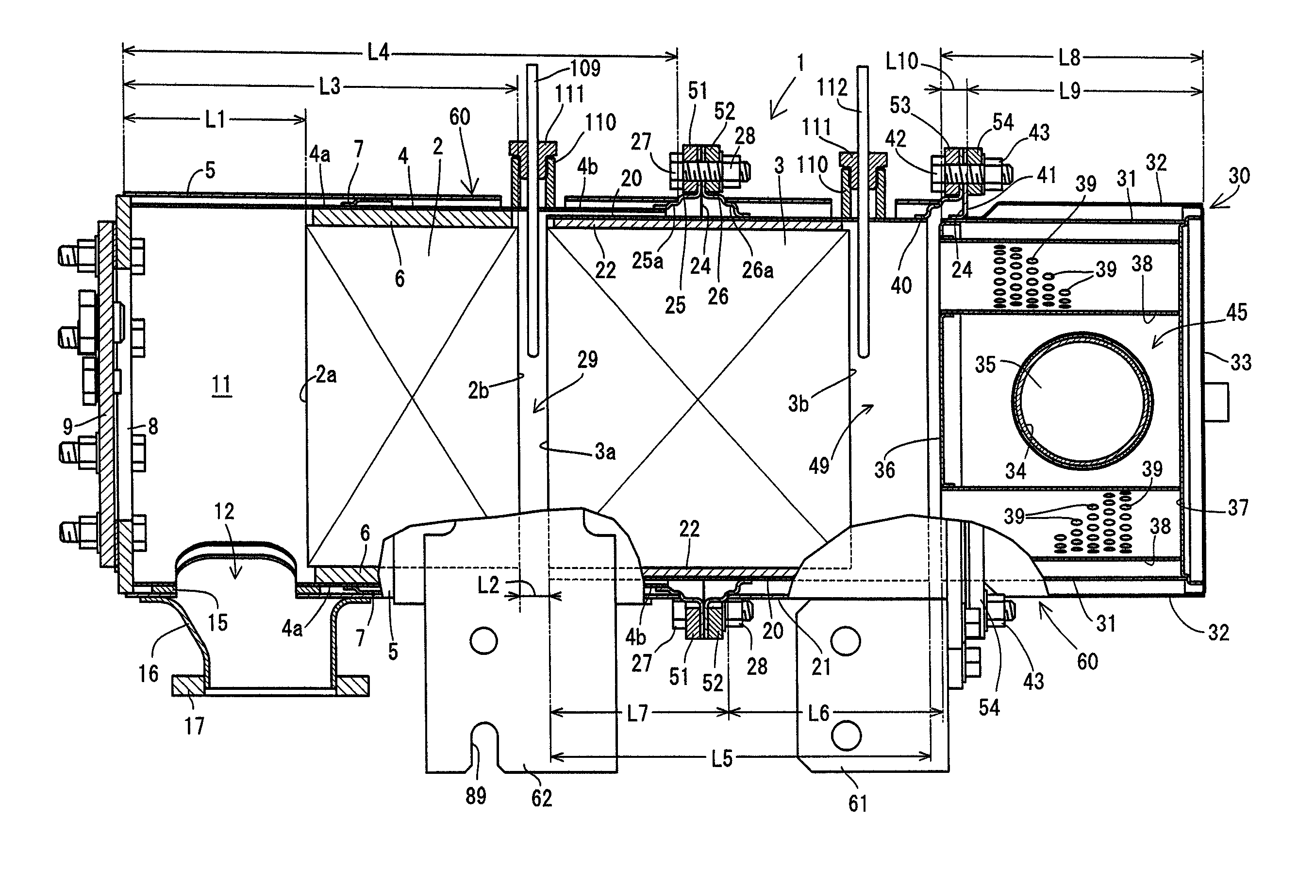
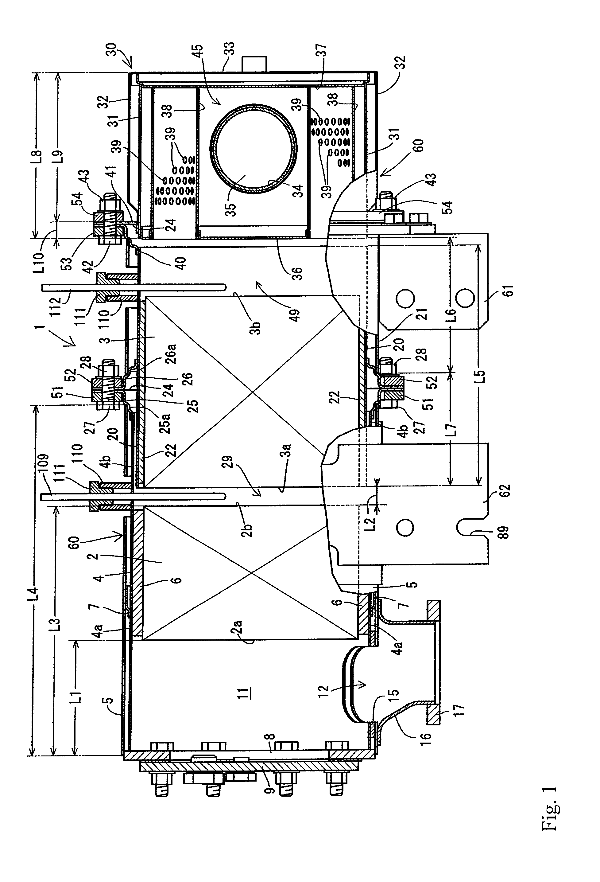
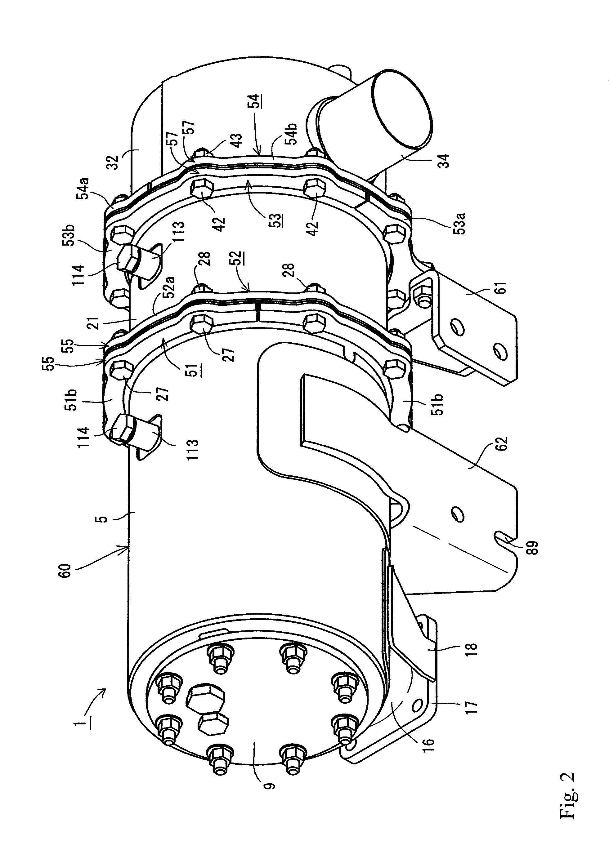
[0050]A description will be given below of a first embodiment of an exhaust gas purification device obtained by embodying the present invention on the basis of the accompanying drawings with reference to FIG. 1 to FIG. 13. It is provided with a continuous regeneration type diesel particulate filter 1 (hereinafter, referred to as DPF 1) as an exhaust gas purification device. It is structured such that the DPF 1 reduces a carbon monoxide (CO) and a hydro carbon (HC) in an exhaust gas of a diesel engine 70, in addition to a removal of a particulate matter (PM) in the exhaust gas of the diesel engine 70.

[0051]As shown in FIG. 1, FIG. 6 and FIG. 13, the DPF 1 serving as the exhaust gas purification device is provided for collecting the particulate matter (PM) in the exhaust gas. The DPF 1 is structured as an approximately cylindrical shape which extends long in a lateral direction which intersects an output shaft (a crank shaft) of the diesel engine 70 in a plan view. The DPF 1 is arrang...


PUM


Abstract

A exhaust gas purification device is structured such that it is possible to improve an assembling work ability or a maintenance work ability of gas purifying bodies or exhaust gas purifying cases. In an exhaust gas purification device provided with gas purifying bodies which purify an exhaust gas discharged by an engine, and a gas purifying housing which is provided with the gas purifying bodies therein, the exhaust gas purification device is structured such that a support bracket which supports the gas purifying housing is provided, a bolt hole is formed in the support bracket, an insertion guide is formed in the support bracket, and an attaching bolt is engaged with and disengaged from the bolt hole via the insertion guide.

Description

BACKGROUND OF THE INVENTION[0001]The present invention relates to an exhaust gas purification device which is mounted to a diesel engine or the like, and more particularly to an exhaust gas purification device which removes a particulate matter (a soot and a particulate) and the like which are included in an exhaust gas.[0002]Conventionally, there has been known a technique in which a diesel particulate filter (hereinafter, referred to as DPF) is provided in an exhaust route of a diesel engine as an exhaust gas purification device (an after treatment device), and purifies an exhaust gas which is discharged from the diesel engine by an oxidation catalyst of the DPF or a soot filter (refer, for example, to Patent Documents 1 and 2).[0003]Further, in the DPF, there has been also known a technique of providing a temperature sensor which detects a temperature of an exhaust gas discharged from a diesel engine, and a pressure sensor which detects a pressure of the exhaust gas discharged fr...

Claims


Application Information

Patent Timeline
IPC IPC(8): B01D50/00B01D24/00B01D39/06B01D39/14B01D39/20B01D59/50F01N13/00F01N13/18
CPCF01N13/00F01N13/008F01N13/1805F01N13/1838F01N1/08F01N3/00F01N3/02F01N3/28F01N13/1855
Inventor MITSUDA, MASATAKA
Owner YANMAR POWER TECHNOLOGY CO LTD
Why Eureka
Try Eureka