Pressure sensor for vehicle and brake fluid pressure control apparatus for vehicle

Inactive Publication Date: 2009-02-12
NAGANO KEIKI
View PDF7 Cites 0 Cited by
  • Summary
  • Abstract
  • Description
  • Claims
  • Application Information

AI Technical Summary

Benefits of technology

[0032]1. In accordance with the pressure sensor for the vehicle of the present invention, it is possible to prevent contamination from being generated between the contact probe and the sensing element that may be caused by influence of the environment around the pressure sensor or the slide of the contact probe, which allows to improve the reliability of the connection in the long term. Furthermore, the electrical contact resistance between the contact probe and the sensing element can be prevented from being increased. Moreover, the position of the contact probe can be easily determined when assembling the contact probe into the sensor housing. Thus, workability of assembling the contact probe into the sensor hous

Problems solved by technology

In the conventional pressure sensor, because the contact probe 630 is slidably disposed in the insertion hole 22c of the sensor housing 20 and the position of the contact probe 630 is not securely fixed, contamination, which is adhesion of dust between the sensing element 10 and the contact probe 630, may be caused by the influences of environment around the sensing element 10 or the sliding of the contact probe 630, which causes a problem t

Method used


Image

  • Pressure sensor for vehicle and brake fluid pressure control apparatus for vehicle
  • Pressure sensor for vehicle and brake fluid pressure control apparatus for vehicle
  • Pressure sensor for vehicle and brake fluid pressure control apparatus for vehicle

Examples


Example

[0045]Embodiment of the invention is described in detail below with reference to the accompanying drawings. For describing the embodiment, the explanation below uses as an example a pressure sensor installed in a brake fluid pressure control apparatus for a vehicle that can perform anti-lock control, traction control and the like.

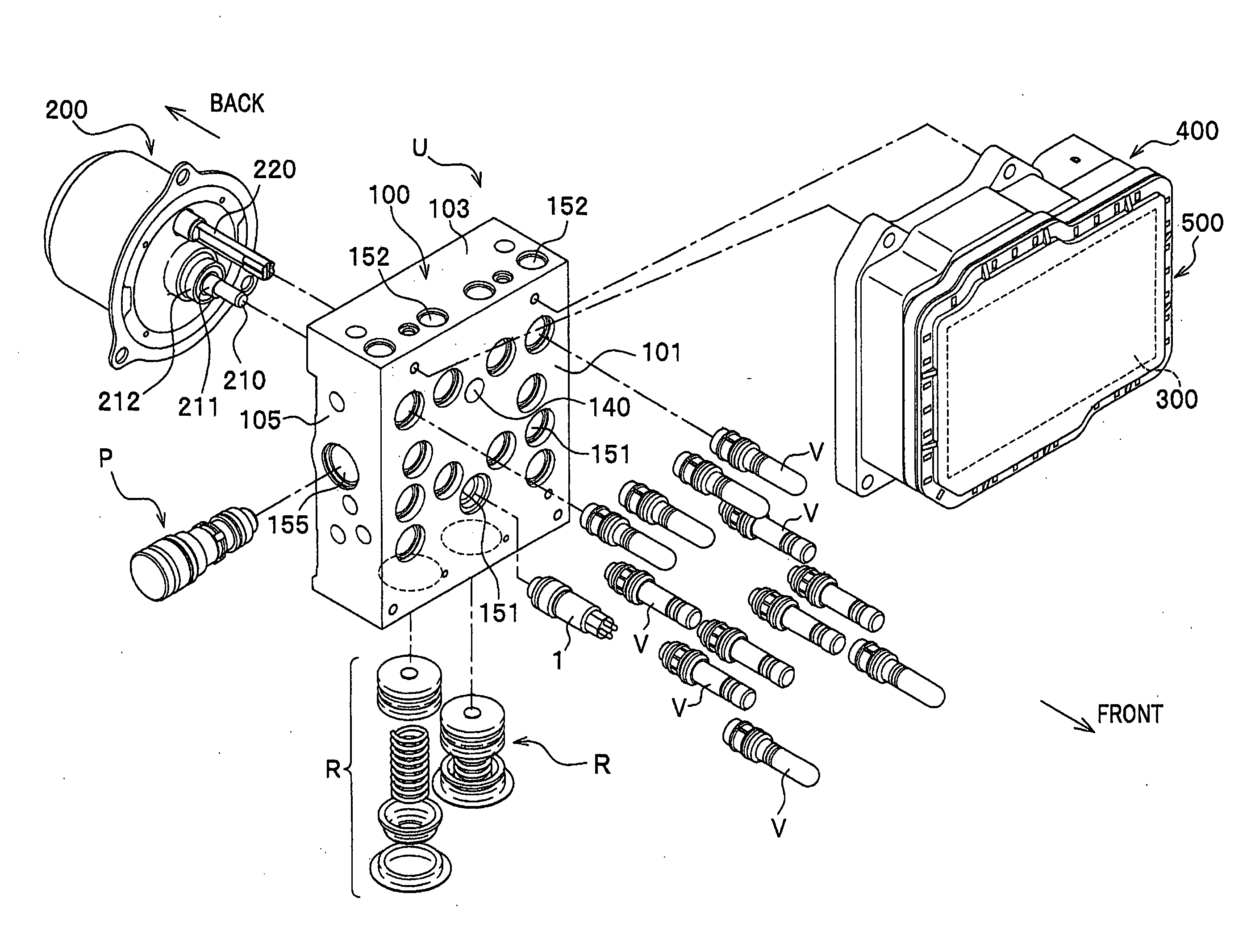
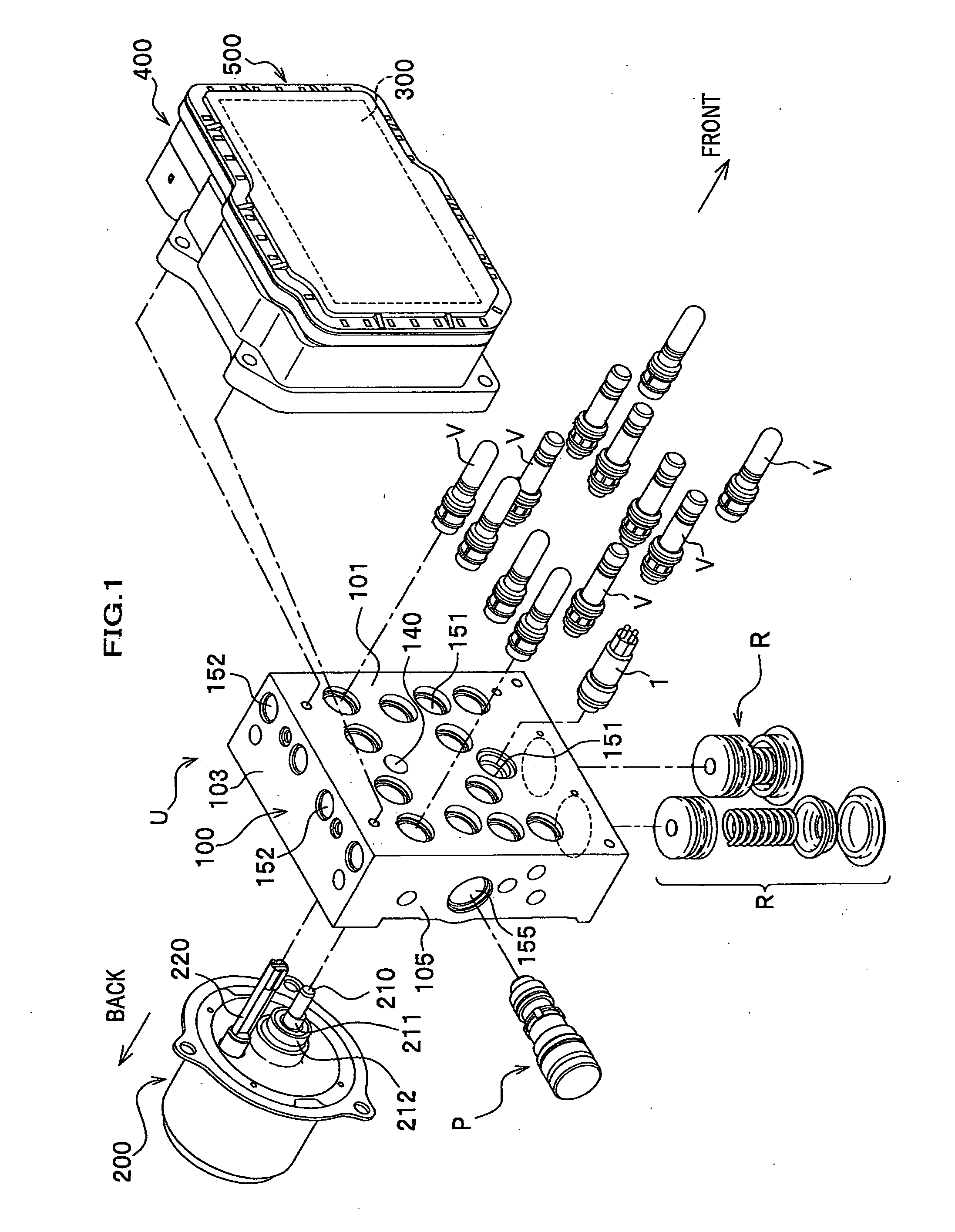
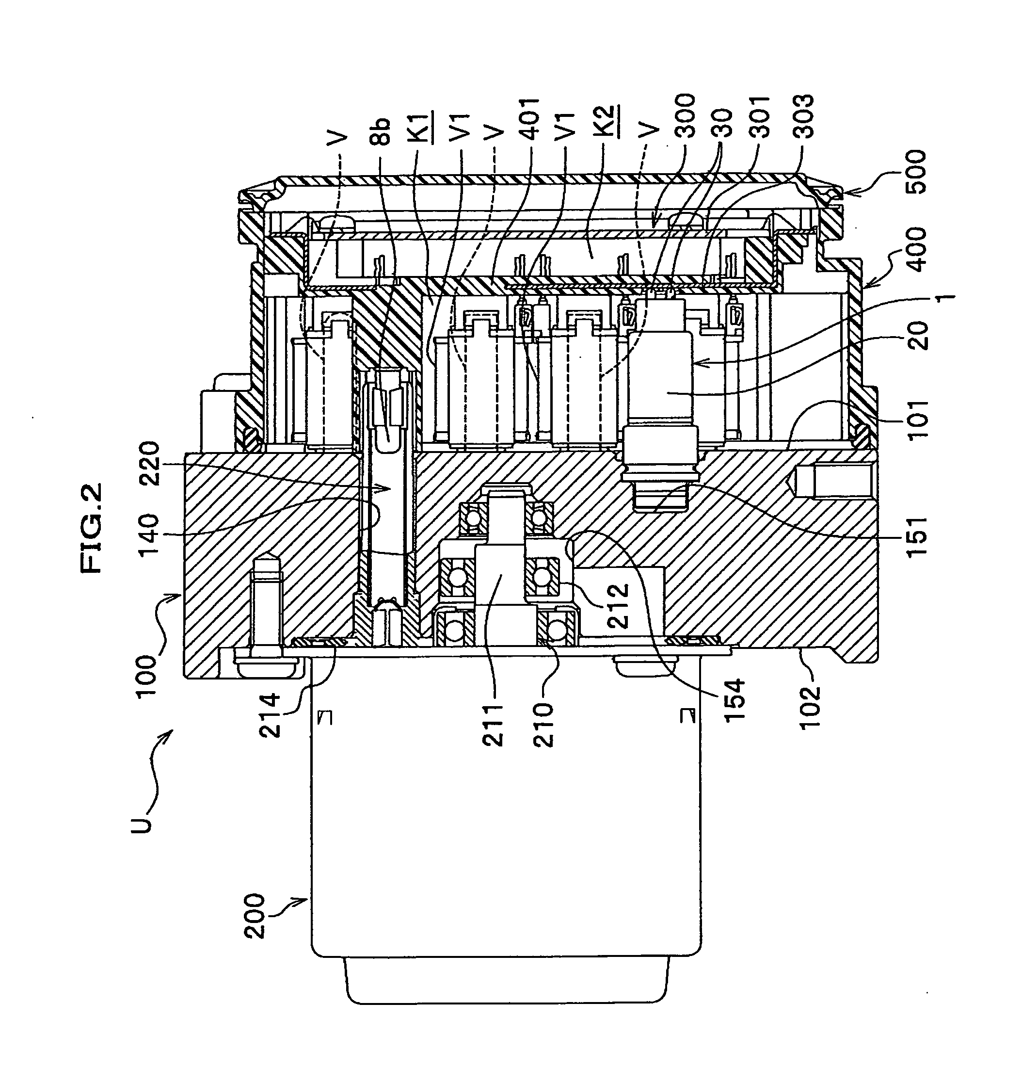
[0046]The configuration of a brake fluid control apparatus for a vehicle U is described below with reference to FIG. 1. The brake fluid control apparatus for a vehicle U includes a base 100 on which electrical parts, such as electromagnetic valves V and a pressure sensor 1, and a reciprocating pump P are mounted, a motor 200 which is the power source of the reciprocating pump P, an electronic control unit 300 that controls opening and closing of the electromagnetic valves V and the operation of the motor 200, a housing 400 that accommodates the electrical parts protruding from the base 100 and the electronic control unit 300, and a cover 500 that covers the...


PUM


Abstract

Disclosed is a pressure sensor 1 for a vehicle including a sensing element 10 for measuring the pressure of brake fluids in fluid passages, a sensor housing 20 for accommodating the sensing element 10, and contact probes 30 that are electrically connected to the sensing element 10 and an electronic control unit 300 (control unit). Each contact probe 30 includes a sleeve 31, a coil spring 32 (elastic member) housed in the sleeve 31, the rod 33 inserted into the sleeve 31. The sleeve 31 is connected to the sensing element 10 in a state that the sleeve 31 is fixed in the sensor housing 20, and the rod 33 is pressed to the electronic unit 300 by pressing force of the coil spring 32.

Description

CROSS REFERENCE TO RELATED APPLICATIONS[0001]This application claims the foreign priority benefit under 35 U.S.C. §119 of Japanese Patent Application No. 2007-209160 filed on Aug. 10, 2007, the disclosure of which is incorporated herein by reference.BACKGROUND OF THE INVENTION[0002]1. Field of the Invention[0003]The present invention is related to a pressure sensor for a vehicle and a brake fluid pressure control apparatus for a vehicle equipped with the pressure sensor.[0004]2. Description of the Related Art[0005]In a brake fluid pressure control apparatus for a vehicle that controls the brake fluid pressure applied to vehicle brakes, an electronic control unit controls various parts provided in fluid passages based on the pressure of brake fluid measured by a pressure sensor.[0006]A conventional pressure sensor includes a sensing element 10 for measuring the pressure of brake fluid in fluid passages, a sensor housing 20 for accommodating the sensing element 10 and a contact probe ...

Claims


Application Information

Patent Timeline
IPC IPC(8): G01L19/00
CPCF15B13/086B60T8/368
Inventor SHINOHARA, TATSUYANAKANO, MASAHIKOIMAI, ATSUSHITOMOMATSU, YOSHIHIRO
Owner NAGANO KEIKI
Why Eureka
Try Eureka