Imaging lens
a technology of imaging lens and lens body, applied in the field of imaging lens, can solve the problems of difficult peripheral aberration correction, inability to obtain excellent optical performance, etc., and achieve the effect of small radius, reduced imaging lens profile, and reduced radius of sixth lens
- Summary
- Abstract
- Description
- Claims
- Application Information
AI Technical Summary
Benefits of technology
Problems solved by technology
Method used
Image

Examples
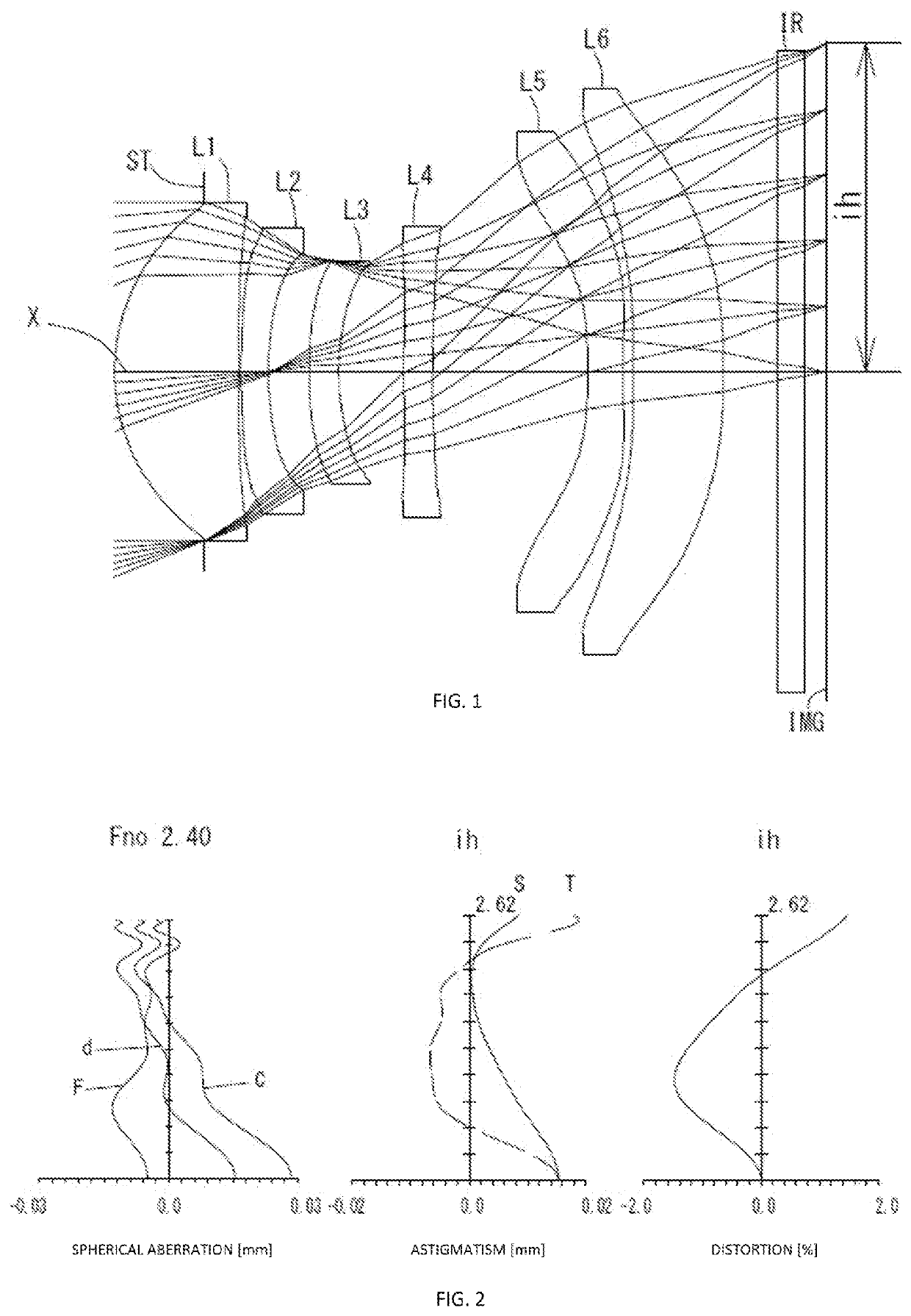
example 1
[0153]The basic lens data is shown below in Table 1.
TABLE 1Example 1Unit mmf = 6.51Fno = 2.40ω(°) = 21.7ih = 2.62TTL = 5.63Surface DatairdNdνd(Object)InfinityInfinity1 (Stop)Infinity−0.72352*1.56650.99401.54455.86(νd1)3*16.55180.02004*4.69100.22001.67119.24(νd2)5*2.31880.32486*2.47070.24001.53555.66(νd3)7*1.78120.52238*6.91020.23021.67119.24(νd4)9*6.02191.249510* −4.36400.28001.54455.86(νd5)11* 5.69950.080712* 45.97760.72561.67119.24(νd6)13* −7.47630.437114 Infinity0.21001.51764.2015 Infinity0.1693Image PlaneInfinityConstituent Lens DataLensStart SurfaceFocal LengthEntrance Pupil Diameter123.106EPd2.71324−7.10136−13.58148−77.9465104.4976129.640Aspheric Surface DataFirst SurfaceSecond SurfaceThird SurfaceFourth SurfaceFifth SurfaceSixth Surfacek−5.135449E−024.410936E+000.000000E+000.000000E+000.000000E+000.000000E+00A4 3.403827E−03−7.184669E−02 −1.576998E−01 −1.347101E−01 −2.045517E−01 −2.093735E−01 A6−4.401221E−031.655043E−013.030989E−013.184388E−014.341483E−014.669668E−01A8−7.80787...
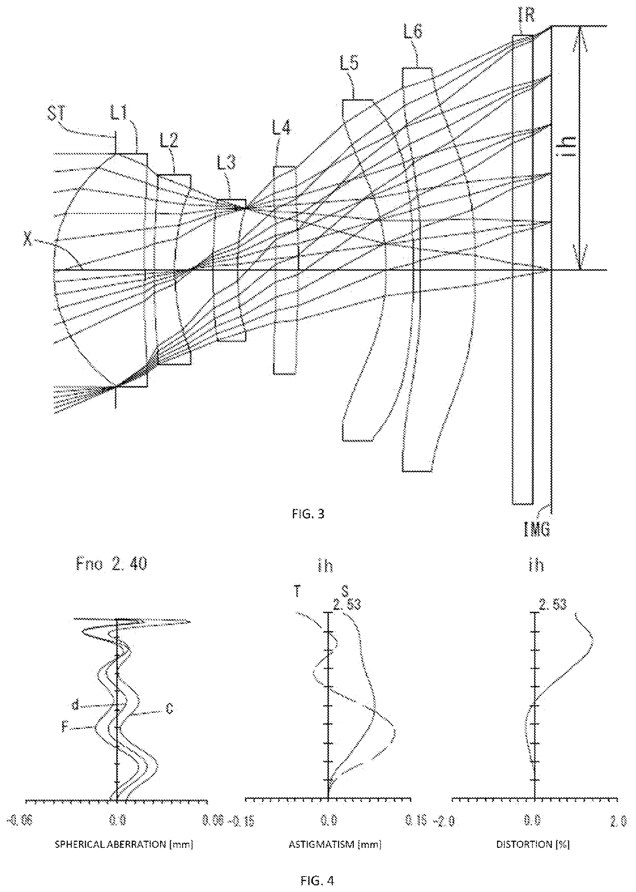
example 2
[0156]The basic lens data is shown below in Table 2.
TABLE 2Example 2Unit mmf = 5.85Fno = 2.40ω(°) = 23.2ih = 2.53TTL = 5.13Surface DatairdNdνd(Object)InfinityInfinity1 (Stop)Infinity−0.64642*1.43900.95231.54456.44(νd1)3*−66.49530.09414*6.76900.22001.67119.24(νd2)5*2.09720.39716*4.84670.25761.53555.69(νd3)7*2.55360.40008*13.28820.23001.67119.24(νd4)9*30.66000.925010* −2.41610.28001.54456.44(νd5)11* 33.66840.080012* 44.73100.57381.67119.24(νd6)13* −7.58520.391014 Infinity0.21001.51764.2015 Infinity0.1916Image PlaneInfinityContintuent Lens DataLensStart SurfaceFocal LengthEntrance Pupil Diameter122.600EPd2.43924−4.61736−10.5034834.7805104.1296129.712Aspheric Surface DataFirst SurfaceSecond SurfaceThird SurfaceFourth SurfaceFifth SurfaceSixth Surfacek−3.263512E−020.000000E+000.000000E+000.000000E+000.000000E+000.000000E+00A4−2.705287E−024.952865E−02−1.311782E−01 −2.886808E−01 −2.216541E−01 −2.467413E−01 A6 1.892406E−01−1.206645E−02 4.711064E−011.343067E+004.570970E−017.493984E−01A8−6.86...
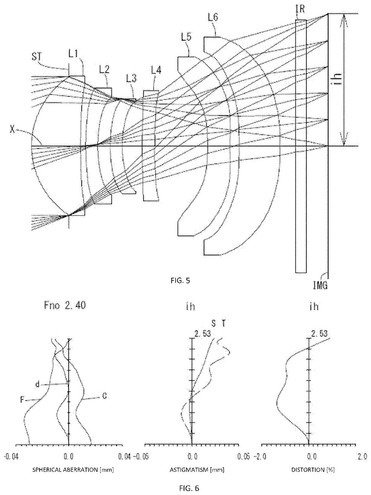
example 3
[0159]The basic lens data is shown below in Table 3.
TABLE 3Example 3Unit mmf = 6.41Fno = 2.40ω(°) = 21.4ih = 2.53TTL = 5.63Surface DatairdNdνd(Object)InfinityInfinity1 (Stop)Infinity−0.72002*1.55940.93991.54456.44(νd1)3*9.50150.10004*4.15720.23161.67119.24(νd2)5*2.27670.23796*2.22890.23001.53555.69(νd3)7*1.78590.38558*5.64850.23671.67119.24(νd4)9*5.12701.023410* −4.42570.42791.54456.44(νd5)11* 7.89040.176212* 41.04730.78721.67119.24(νd6)13* −8.08690.300014 Infinity0.21001.51764.2015 Infinity0.4196Image PlaneInfinityConstituent Lens DataLensStart SurfaceFocal LengthEntrance Pupil Diameter123.289EPd2.67124−7.89436−20.51448−101.246510−5.14561214.872Aspheric Surface DataFirst SurfaceSecond SurfaceThird SurfaceFourth SurfaceFifth SurfaceSixth Surfacek 0.000000E+000.000000E+000.000000E+000.000000E+000.000000E+000.000000E+00A4−3.651960E−03−7.593647E−02 −1.551401E−01 −1.440891E−01 −1.986046E−01 −2.043804E−01 A6−2.950736E−031.651540E−013.003166E−013.215576E−014.381340E−014.659481E−01A8−7.699...
PUM
 Abstract
Description
Claims
Application Information
 - R&D
- Intellectual Property
- Life Sciences
- Materials
- Tech Scout
- Unparalleled Data Quality
- Higher Quality Content
- 60% Fewer Hallucinations
Browse by: Latest US Patents, China's latest patents, Technical Efficacy Thesaurus, Application Domain, Technology Topic, Popular Technical Reports.
© 2025 PatSnap. All rights reserved.Legal|Privacy policy|Modern Slavery Act Transparency Statement|Sitemap|About US| Contact US: help@patsnap.com