Antenna Radiator with Pre-Configured Cloaking to Enable Dense Placement of Radiators of Multiple Bands

a radiator and antenna technology, applied in the field of wireless communication, can solve the problems of affecting the performance of the antenna in the c-band band, affecting the performance of the antenna in the lower band radiator, and affecting the practical

Active Publication Date: 2021-11-18
JOHN MEZZALINGUA ASSOC LLC
View PDF0 Cites 2 Cited by
  • Summary
  • Abstract
  • Description
  • Claims
  • Application Information

AI Technical Summary

Benefits of technology

[0008]Another aspect of the present invention involves an antenna. The antenna comprises a plurality of mid band radiators; a plurality of high band radiators; and a plurality of low band radiators, wherein the plurality of low band radiators includes a first subset of low band radiators that are in close proximity to one or more of the plurality of mid band radiators and a second subset of low band radiators that are in close proximity to one or more of the plurality of high band radiators, wherein each of the low band radiators includes a plurality of low band dipole arms, each of the low band dipole arms having a central conductor, a mantle disposed on an outer surface of the central conductor, and a conductive pattern disposed on an outer surface of the mantle, werein the low band radiators in the first subset of low band radiators have a first conductive pattern, and the low band radiators in the second subset of low band radiators have a second conductive pattern, wherein the first conductive pattern is different from the second conductive pattern, wherein the first conductive pattern is configured to prevent a mid band re-radiation and the second conductive pattern is configured to prevent a high band re-radiation.

Problems solved by technology

A challenge arises in integrating C-Band or CBRS radiators into antennas designed to operate in the existing lower bands in that energy radiated by the C-Band radiators may cause resonances in the lower band radiators.
A particular problem may arise in the low band radiators that are in close proximity to the C-Band radiators whereby the low band radiators may significantly degrade the performance of the antenna in the C-Band band.
The same is true for low band radiators that are in close proximity to mid band radiators, whereby energy emitted by the mid band radiators causes resonance in the low band radiators, which subsequently re-radiates to interfere with the mid band radiators radiation patterns.
This is generally not practical because increasing the area of the antenna exacerbates wind loading, which can have severe consequences with multiple antennas deployed on tall cell towers.
Further, given limited space availability on a given cell tower, or in a typical urban deployment, it is generally not feasible to simply increase the size of the antenna.

Method used


Image

  • Antenna Radiator with Pre-Configured Cloaking to Enable Dense Placement of Radiators of Multiple Bands
  • Antenna Radiator with Pre-Configured Cloaking to Enable Dense Placement of Radiators of Multiple Bands
  • Antenna Radiator with Pre-Configured Cloaking to Enable Dense Placement of Radiators of Multiple Bands

Examples


Embodiment Construction

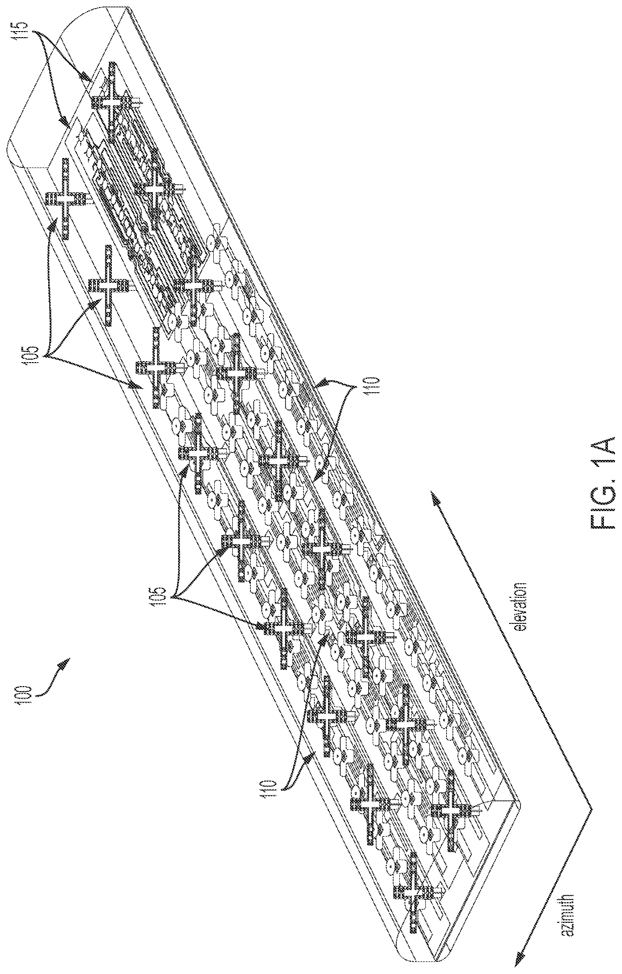
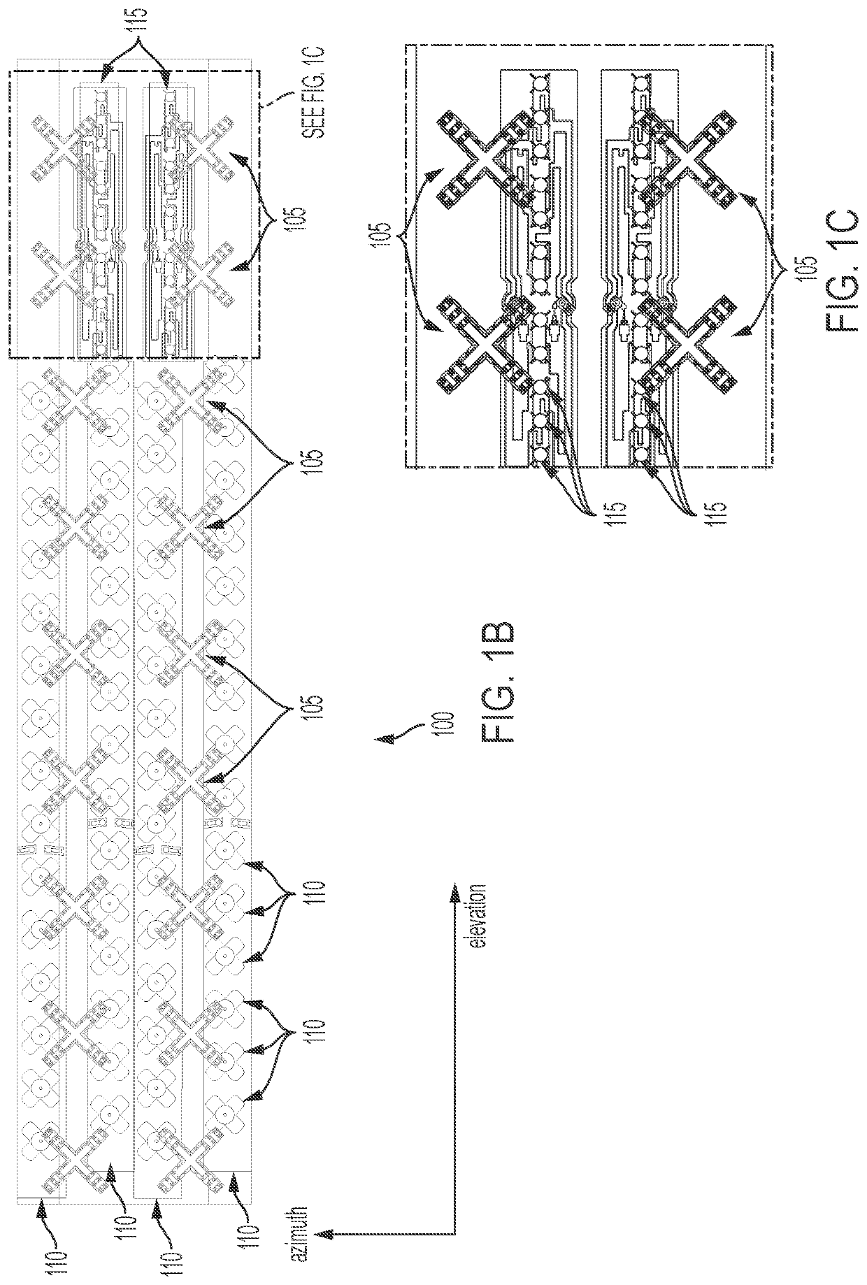
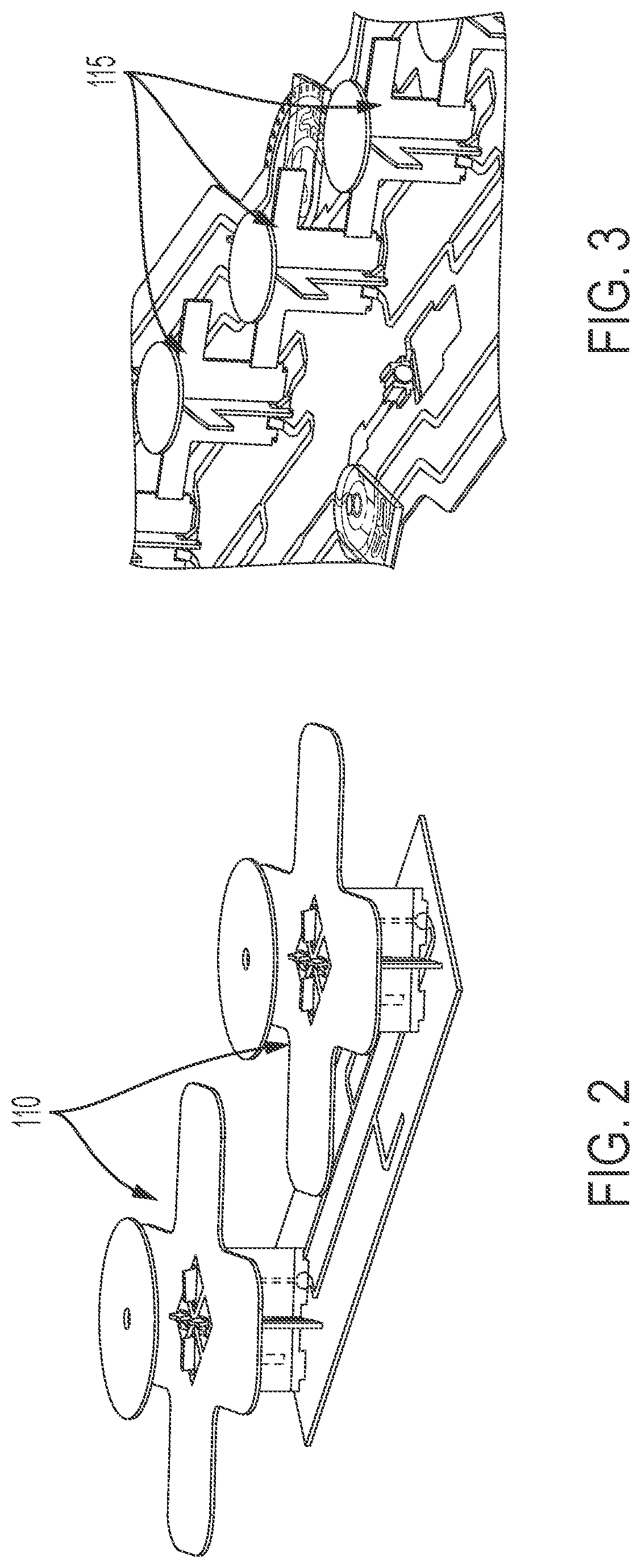
[0023]FIG. 1A illustrates an exemplary array face 100 according to a first embodiment of the disclosure. Array face 100 has a plurality of low band radiators 105 (for example, 617-960 MHz) that are arranged in two columns along the elevation axis of the antenna; a plurality of mid band radiators 110 (for example, 1.695-2.7 GHz) that are arranged in four columns and only extend for a portion of the antenna length along the elevation axis; and a plurality of C-Band radiators 115 (for example, 3.4-4.2 GHz) (as used herein, the C-Band radiators may be referred to as high band radiators) that are arranged in two columns along a remaining length array face 100 along the elevation axis. Each of the low band radiators 105, mid band radiators 110, and C-Band radiators 115 comprise two orthogonal radiator arms, each of which radiate in a single polarization. Accordingly, each of the radiators illustrated may operate independently in two orthogonal polarizations (“dual polarized”), for example...


PUM


Abstract

Disclosed is an antenna that enables dense packing of low band, mid band, and C-band radiators. The low band radiators have a plurality of dipole arms that minimize re-radiation of either RF energy emitted by either the mid band or C-Band radiators. In one embodiment, the dipole arms are formed of a two-dimensional structure that has a shape that substantially prevents re-radiation in both the mid band and the C-band. In another embodiment, the dipole arms have two different configurations: a first configuration optimized for preventing re-radiation in the mid band, and a second configuration optimized for preventing re-radiation in the C-Band. In the latter embodiment, the low band radiators in close proximity to the mid band radiators have dipole arms of the first configuration, and the low band radiators in close proximity to the C-Band radiators have dipole arms of the second configuration.

Description

BACKGROUND OF THE INVENTION[0001]This application is claims priority to United States Provisional Patent Application Ser. No. 63 / 025,659, filed May 15, 2020, pending, which application is hereby incorporated by this reference in its entirety as if fully set forth herein.FIELD OF THE INVENTION[0002]The present invention relates to wireless communications, and more particularly, to compact multiband antennas.RELATED ART[0003]The introduction of additional spectrum for cellular communications, such as the C-Band frequencies and Citizens Broadband Radio Service (CBRS) bands, opens up vast resources of additional capacity for existing cellular customers as well as new User Equipment (UE) types. New UE types include Internet of Things (IoT) devices, drones, and self-driving vehicles. Further, the advent of CBRS (or C-Band, which encompasses the CBRS channels) enables a whole new cellular communication paradigm in private networks.[0004]Accommodating CBRS in existing LTE and 5G cellular ne...

Claims


Application Information

Patent Timeline
Patent Type & Authority Applications(United States)
IPC IPC(8): H01Q5/48H01Q5/314H01Q1/38H01Q21/06
CPCH01Q5/48H01Q5/314H01Q1/246H01Q21/062H01Q1/38H01Q5/42H01Q25/001H01Q21/24H01Q15/006
Inventor SUNDARARAJAN, NIRANJANBUONDELMONTE, CHARLESZHU, JAYCHEN, WENGANG
Owner JOHN MEZZALINGUA ASSOC LLC
Why Eureka
Try Eureka