Machine for driving an electric generator
- Summary
- Abstract
- Description
- Claims
- Application Information
AI Technical Summary
Benefits of technology
Problems solved by technology
Method used
Image

Examples
Embodiment Construction
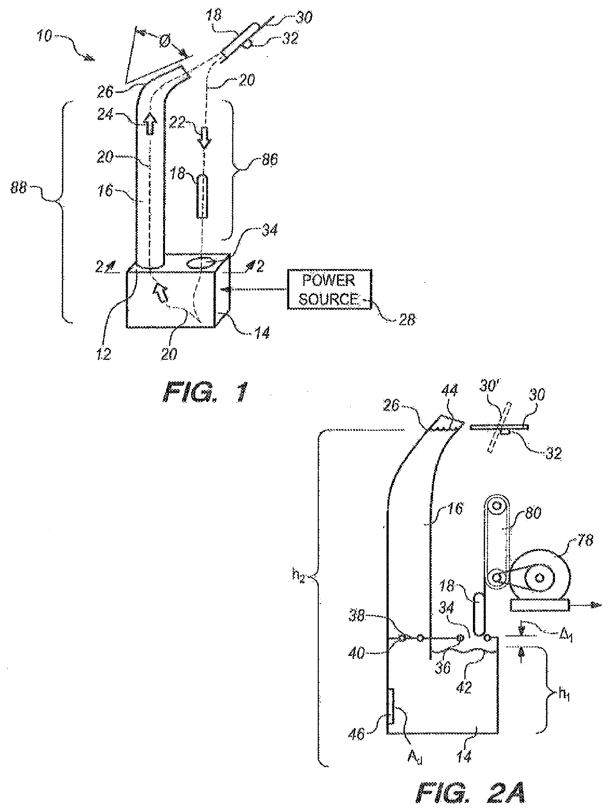
[0093]Referring initially to FIG. 1, a machine in accordance with the present invention is shown and is generally designated 10, As shown, the machine 10 includes a bi-level tank 12 that has a both a lower transfer tank 14 and an upper return tank 16. The operational purpose of the machine 10 is to move a power module 18 through a duty cycle on a closed-loop pathway 20 which is generally designated by the dashed line 20 in FIG. 1. Further, as shown in FIG. 1, a duty cycle on closed-loop pathway 20 includes a DOWN portion, indicated by the arrow 22, and an UP portion, indicated by the arrow 24. FIG. 1 also shows that the machine 10 includes a deflector / exit chute 26 that is connected to the top of the return tank 16 for directing the power module 18 as it leaves the bi-level tank 12. As will be appreciated with the additional disclosure presented below, an important consideration for the machine 10 is that it requires an external power source 28 for its operation. As envisioned for t...
PUM
 Abstract
Description
Claims
Application Information
 - R&D
- Intellectual Property
- Life Sciences
- Materials
- Tech Scout
- Unparalleled Data Quality
- Higher Quality Content
- 60% Fewer Hallucinations
Browse by: Latest US Patents, China's latest patents, Technical Efficacy Thesaurus, Application Domain, Technology Topic, Popular Technical Reports.
© 2025 PatSnap. All rights reserved.Legal|Privacy policy|Modern Slavery Act Transparency Statement|Sitemap|About US| Contact US: help@patsnap.com