Eureka AIR delivers breakthrough ideas for toughest innovation challenges, trusted by R&D personnel around the world.

Work Machine Drive Train Torque Vectoring Based on Work Cycle Recognition

a work machine and work cycle recognition technology, applied in the field of hauling machines, can solve the problems of wasting power from the drive train, affecting the lifting of the rear axle, and partially or completely off the ground of the ground

Inactive Publication Date: 2014-02-06
CATERPILLAR INC
View PDF3 Cites 37 Cited by
  • Summary
  • Abstract
  • Description
  • Claims
  • Application Information

AI Technical Summary

Benefits of technology

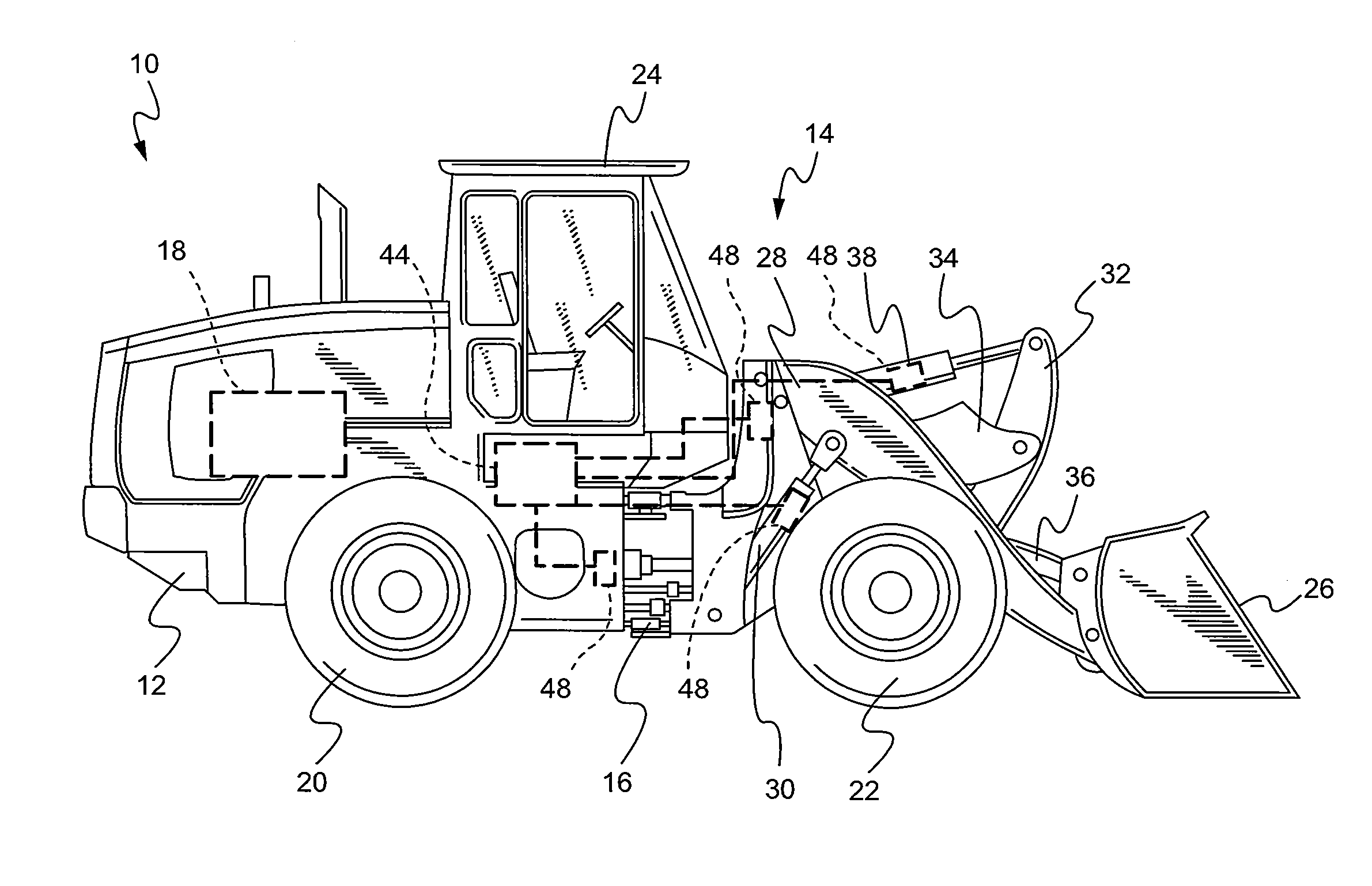
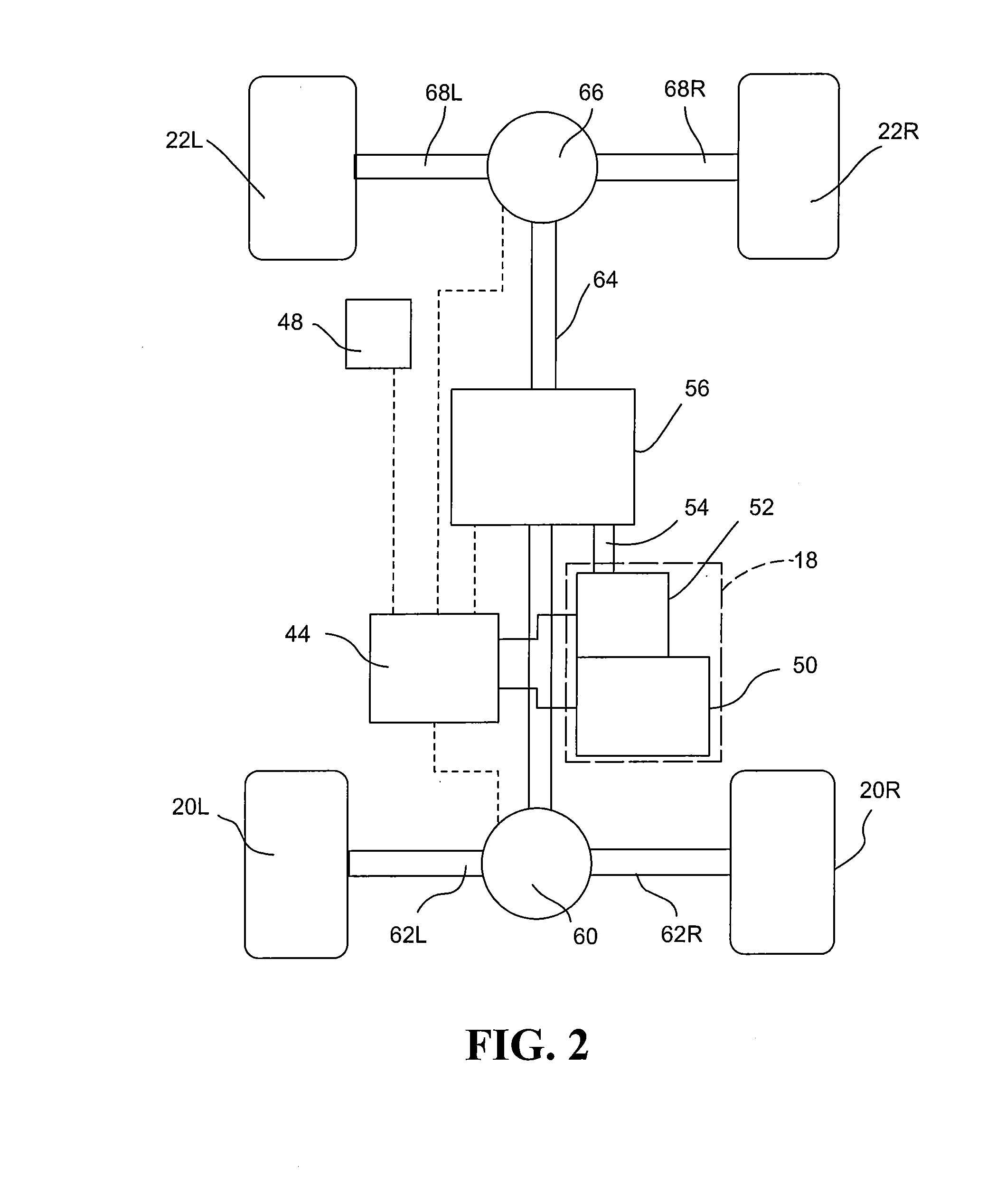
This patent describes a machine that can distribute its power between its front and rear wheels based on the work cycle step being performed by the machine. This is done through a torque transfer unit that can transfer different amounts of torque to the front and rear wheels. The machine can detect the work cycle step based on the operating parameters it uses, and the control unit will adjust the distribution of power to match the desired front and rear torque for that step. This allows the machine to work more efficiently and perform multiple work cycle steps with greater efficiency.

Problems solved by technology

Aggressive digging or overloading of the bucket can cause the rear axle to lift partially or completely off of the ground.
In some situations, the torque provided to the lightly loaded wheels may be sufficient to cause the wheels to slip and thereby waste power from the drive train that could be utilized to drive the work machine over the ground.
Measuring loads independently at each wheel of the vehicle likely entails adding components and cost to the vehicle for performing the measurements in work machines designed for hauling loads of work material of varying size and location at a work site.

Method used


Image

  • Work Machine Drive Train Torque Vectoring Based on Work Cycle Recognition
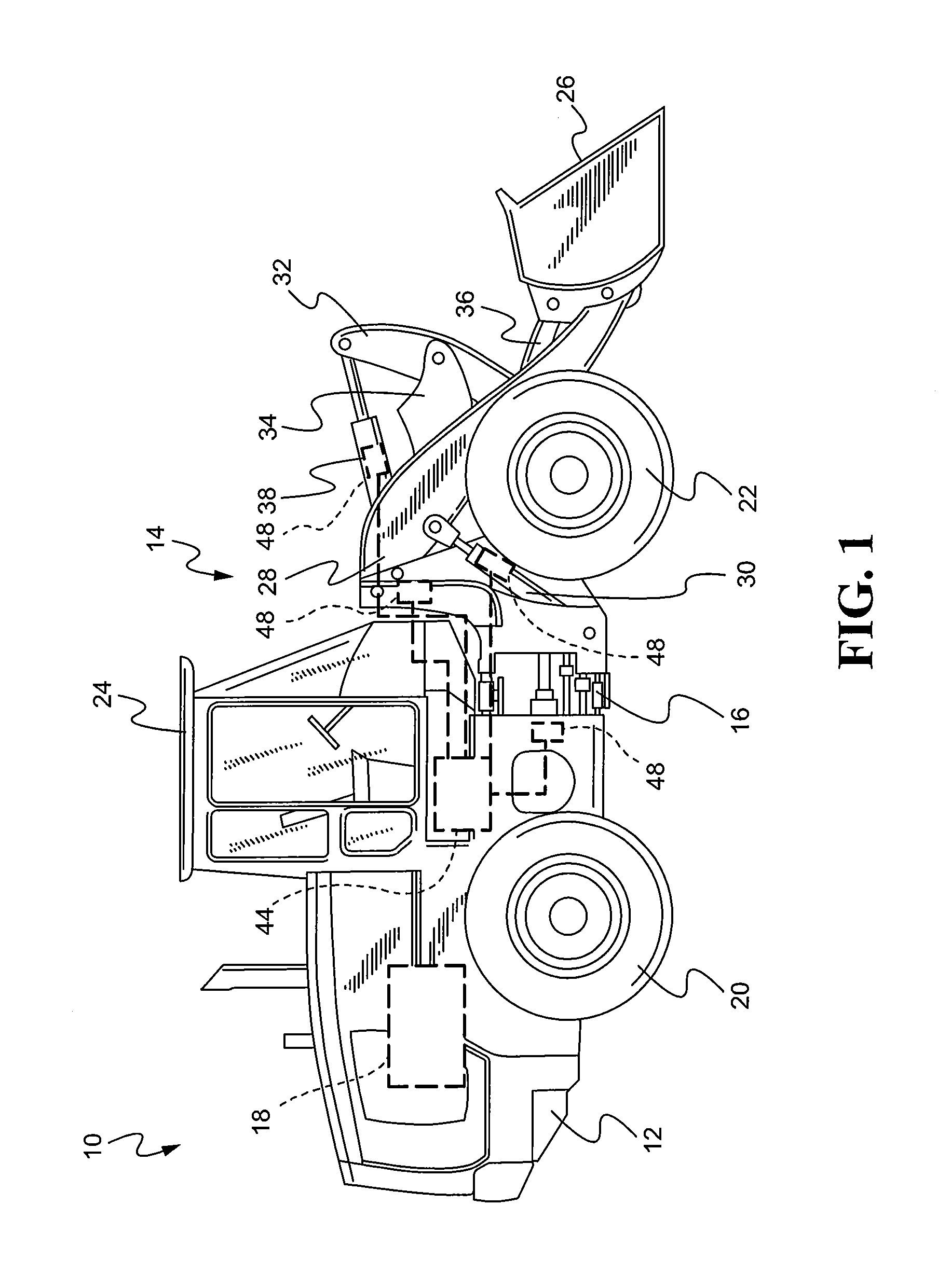
  • Work Machine Drive Train Torque Vectoring Based on Work Cycle Recognition
  • Work Machine Drive Train Torque Vectoring Based on Work Cycle Recognition

Examples


Embodiment Construction

[0031]Although the following text sets forth a detailed description of numerous different embodiments, it should be understood that the legal scope of the invention is defined by the words of the claims set forth at the end of this patent. The detailed description is to be construed as exemplary only and does not describe every possible embodiment since describing every possible embodiment would be impractical, if not impossible. Numerous alternative embodiments could be implemented, using either current technology or technology developed after the filing date of this patent, which would still fall within the scope of the claims defining the scope of protection.

[0032]It should also be understood that, unless a term is expressly defined in this patent using the sentence “As used herein, the term ‘______’ is hereby defined to mean . . . ” or a similar sentence, there is no intent to limit the meaning of that term, either expressly or by implication, beyond its plain or ordinary meanin...


PUM


Abstract

A machine may include a powertrain drivingly connected to the wheels through a torque transfer unit to transfer torque to the front wheels as a function of a desired front torque and to the rear wheels as a function of a desired rear torque. At least one sensor of the machine may detect a value of an operating parameter indicative of a work cycle step being performed by the machine. A control unit determines the work cycle step being performed as a function of the value of the parameter, and the desired front and rear torques as a function of the work cycle step. The control unit also considers the weight and position of a load of material borne by an implement of the machine in determining the work cycle step being performed.

Description

TECHNICAL FIELD[0001]This disclosure relates generally to machines for hauling material and, in particular, to drive trains in such machines distributing torque to the wheels of the machine based on a work cycle step being performed by the machine, a weight distribution of a load, the speed and direction of the machine, and the terrain over which the machine is driven.BACKGROUND[0002]Wheel loaders, rigid frame and articulated dump trucks and other machines known in the art are used for moving material from one place to another at a worksite. In loading and moving the work material, these work machines are subjected to varying load conditions and weight distributions caused by the movement and positioning of the components of the machine and the load of material being hauled. In a static or non-moving state, the weight distribution of a work machine, such as for example a wheeled front end loader, is affected by component geometry characteristics, including tire radius and tire press...

Claims


Application Information

Patent Timeline
IPC IPC(8): B60W30/188
CPCB60K2023/0816B60K23/0808B60W2510/30B60W2520/22B60W2530/10B60W2720/30B60W2720/403
Inventor JENSEN, JEFFREY EDWARD
Owner CATERPILLAR INC
Why Eureka
Eureka Blog
Learn More