Piezoelectrically actuated fuel injection valve

a fuel injection valve and piezoelectric actuator technology, applied in the field of valves, can solve problems such as piezoelectric actuator, loss of pressure chamber liquid, and length compensation

Inactive Publication Date: 2001-01-02
ROBERT BOSCH GMBH
View PDF6 Cites 39 Cited by
  • Summary
  • Abstract
  • Description
  • Claims
  • Application Information

AI Technical Summary

Problems solved by technology

In such valves, there is the problem of compensating for changes in length of the piezoelectric actuator, the valve, the enclosed pressure chamber liquid, or the valve housing by means of the hydraulic coupling chamber.
Since, to open the valve, the piezoelectric actuator generates a pressure in the pressure chamber, this pressure also leads to a loss of pressure chamber liquid.
A device which is supposed to effect such refilling is indeed already known from the prior art defined

Method used


Image

  • Piezoelectrically actuated fuel injection valve
  • Piezoelectrically actuated fuel injection valve
  • Piezoelectrically actuated fuel injection valve

Examples


Embodiment Construction

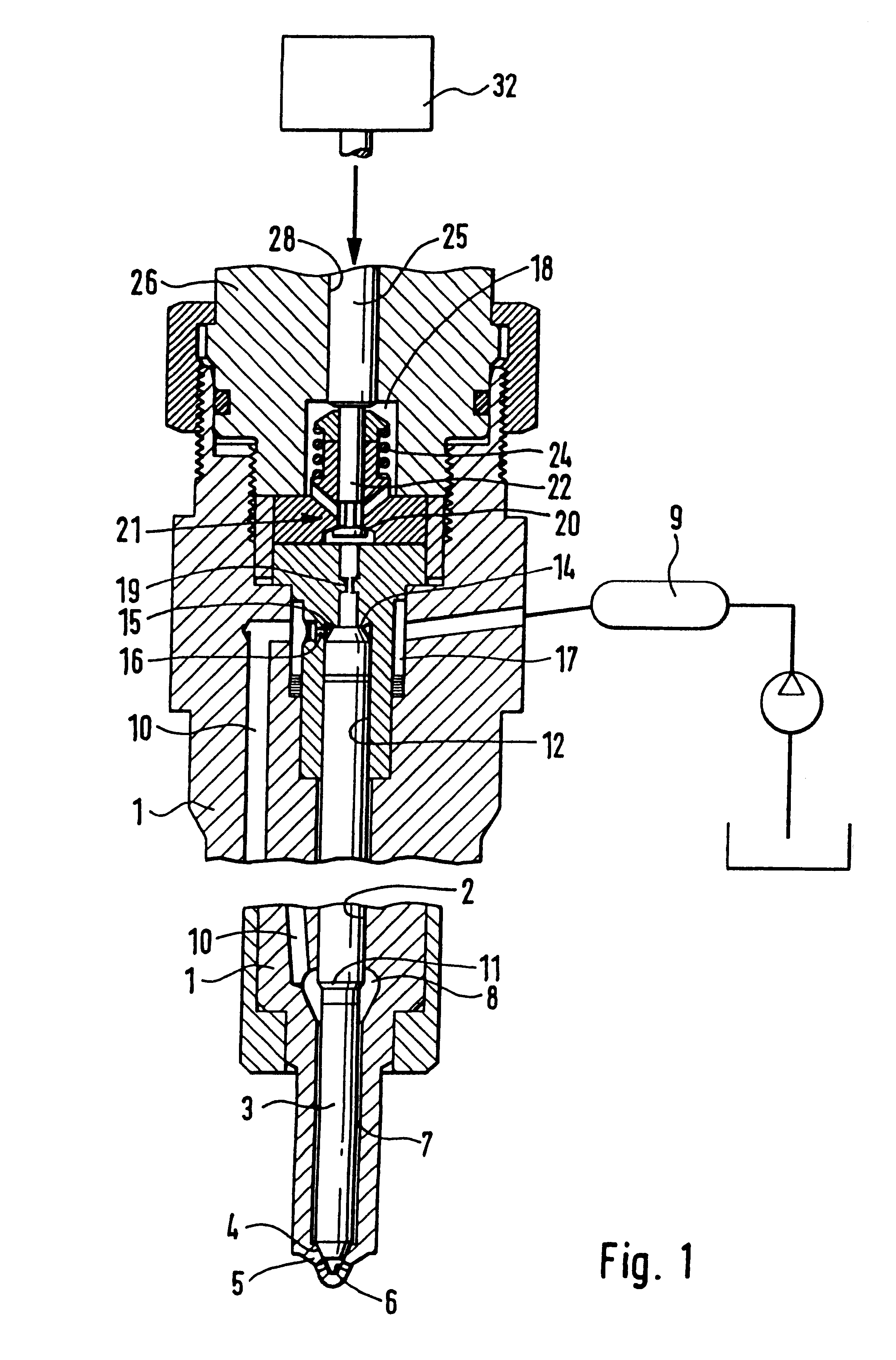
The valve of the invention is used in a fuel injection valve, which is shown in its essential parts in section in FIG. 1. This injection valve has a valve housing 1, in which a valve needle 3 is guided in a longitudinal bore 2; this valve needle can also be prestressed in the closing direction by a closing spring in a known manner and not shown further here. On one end, the valve needle is provided with a conical sealing face 4, which cooperates, on the tip 5 of the valve housing that protrudes into the combustion chamber, with a seat 6 from which injection ports lead away into the interior of the injection valve, in this case connecting the annular chamber 7, filled with fuel under injection pressure, with the combustion chamber so as to execute an injection once the valve needle has lifted from its seat. The annular chamber communicates with a further pressure chamber 8, which is in constant communication with a pressure line 10, by way of which fuel is delivered at injection pres...


PUM


Abstract

A valve for controlling liquids which for its actuation is provided with a liquid-filled coupling chamber, which is disposed between an actuator piston of a piezoelectric actuator and a piston that actuates a valve member. To compensate for liquid losses suffered by the coupling chamber, which is briefly at high in each work cycle, the pressure difference that exists during the return stroke of the actuator piston between the coupling chamber and the opposite sides of the actuator piston and of the that actuates the valve member that are remote from the coupling chamber is utilized to achieve refilling in valveless fashion along gaps. The valve is used for use in fuel injection systems for internal combustion engines of motor vehicles.

Description

PRIOR ARTThe invention relates to a valve for controlling liquids One such valve is known from European Patent Disclosure EP 0 477 700. There, the actuating piston of the valve member is disposed, tightly displaceably, in a smaller-diameter portion of a stepped bore, while conversely a larger-diameter piston which is moved by the piezoelectric actuator is disposed in a larger-diameter portion of the stepped bore. A hydraulic chamber is defined between the two pistons, in such a way that whenever the larger piston is moved a certain distance by the actuator, the actuator piston of the valve member is moved by an increased distance, the increase being due to the step-up ratio of the cross-sectional areas of the stepped bore. The valve member, the actuator piston, the larger-diameter piston and the piezoelectric actuator are located in line with one another along a common axis.In such valves, there is the problem of compensating for changes in length of the piezoelectric actuator, the ...

Claims


Application Information

Patent Timeline
IPC IPC(8): F02M59/00F02M59/46F02M59/20F02M59/36F02M47/00F02M47/02F02M51/00F02M63/00F02M63/02
CPCF02M47/027F02M63/0026F02M63/0035F02M63/0043F02M63/0057F02M63/0225F02M2200/704F02M2200/705F02M2547/003F02M59/02
Inventor HEINZ, RUDOLFKIENZLER, DIETERPOTSCHIN, ROGERSCHMOLL, KLAUS-PETERBOECKING, FRIEDRICH
Owner ROBERT BOSCH GMBH
Why Eureka
Try Eureka