

Functional module and display device having the same
- Summary
- Abstract
- Description
- Claims
- Application Information
AI Technical Summary
Benefits of technology
Problems solved by technology
Method used
Image

Examples
Embodiment Construction
[0044]Reference will now be made in detail to the present embodiments of the invention, examples of which are illustrated in the accompanying drawings. Wherever possible, the same reference numbers are used in the drawings and the description to refer to the same or like parts.
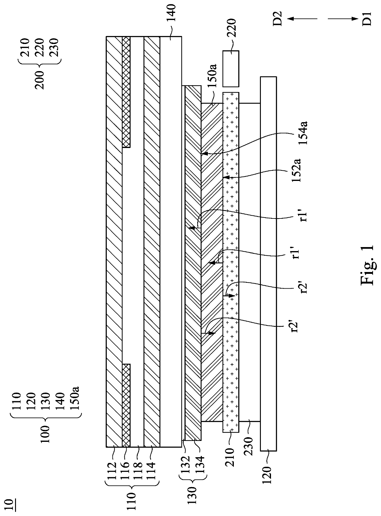
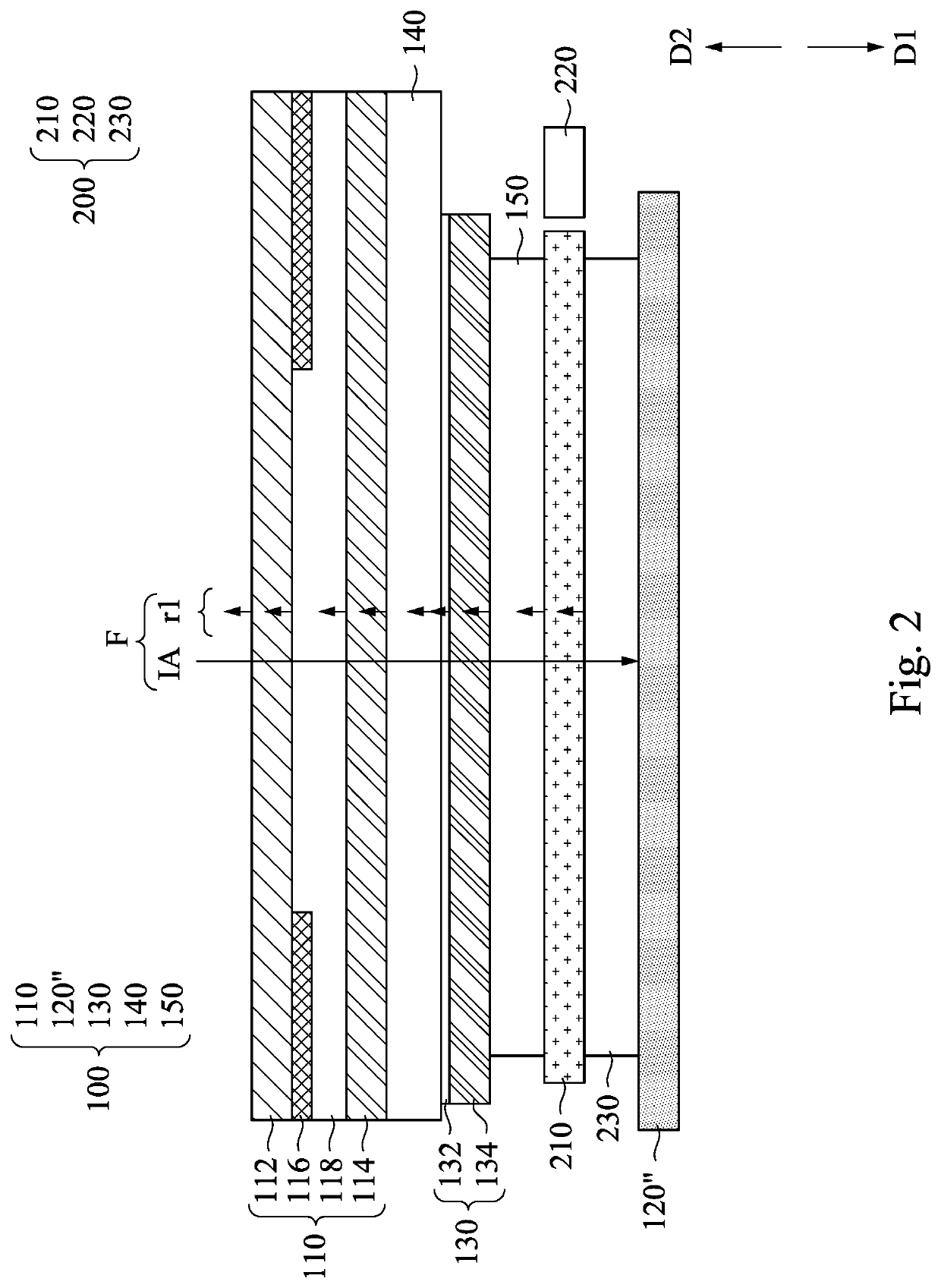
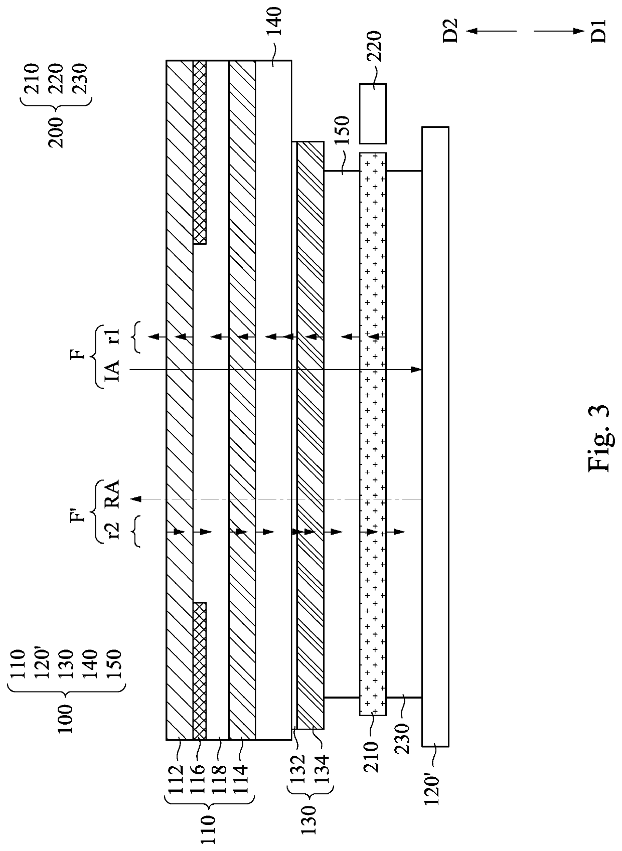
[0045]FIG. 1 is a cross-sectional view of a display device 10 according to one embodiment of the present disclosure. The display device 10 includes a functional module 100 and a front light module 200. The function module 100 includes a composite cover structure 110, a reflective display panel 120, a touch module 130, an optical adhesive layer 140, and a medium layer 150a. The front light module 200 is located between the composite cover structure 110 and the reflective display panel 120. In the present embodiment, the touch module 130 is located between the composite cover structure 110 and the front light module 200, but the present disclosure is not limited in this regard. In some other embodiment, the touc...
PUM
 Abstract
Description
Claims
Application Information