
Knuckle and method of manufacturing knuckle

a manufacturing method and technology of knuckles, applied in the field of knuckles, can solve the problem of increasing the number of man-hours

Inactive Publication Date: 2010-08-19
TOYOTA JIDOSHA KK
View PDF6 Cites 2 Cited by
  • Summary
  • Abstract
  • Description
  • Claims
  • Application Information

AI Technical Summary

Benefits of technology

[0008]The invention provides a knuckle and a method of manufacturing the knuckle that do not cause an increase in the number of man-hours.
[0012]According to this construction, owing to the screw mechanism constructed of simple bolts and simple nuts, the damping member can be fixed to the knuckle by the grip part. The damping member fixing part is constructed by being extruded in the axial direction of the damping member, and the bearing supporting part is constructed by being extruded in the axial direction of the bearing. A construction eliminating a conventionally required bracket for fixing the damping member is thereby obtained. This construction makes it possible to reduce the necessity for machining such as cutting or the like, reduce the number of man-hours for manufacturing the knuckle, and reduce the cost of manufacturing to make the knuckle inexpensive. In addition, the bracket for fixing the damping member can be eliminated. Therefore, the knuckle can be reduced in weight. The bearing is typically a bearing member for rotatably supporting the wheel. This bearing member may be designed such that an inner race and a hub, which constitute the bearing member, are fitted to each other by a serration or the like, or that the inner race itself is integrated with the hub.
[0019]According to this construction, the knuckle can be constructed without using means such as welding or the like, by fixing the bearing to the bearing supporting part by the fixation means and then fixing the bearing supporting part to the damping member fixing part. Accordingly, the occurrence of an inconvenience resulting from heat strain generated in welding can be prevented among the bearing, the bearing supporting part, and the damping member fixing part.
[0022]According to this construction, the knuckle can be constructed in a reduced number of processes by inserting the plurality of the bolts through the through-holes respectively, screwing these bolts into the internal thread parts of the damping member fixing part respectively, and thereby fastening the bearing, the bearing supporting part, and the damping member fixing part together. In this construction, the bearing is typically a bearing member, and it is appropriate to provide the through-holes through an ear portion protruding on an outer periphery side of an outer race constituting this bearing member.
[0025]Thus, the second hole portion for reducing the weight of the bearing supporting part can be provided around the first hole portion. The first and second hole portions also assume the shapes of wall surfaces extending parallel to the axial direction of the bearing member, and are so shaped as to allow direct construction through extrusion.
[0027]According to this construction, the aforementioned knuckle can be manufactured with a construction requiring a reduced number of processes of machining.

Problems solved by technology

In the knuckle thus constructed, especially in the former one of the members, that is, the first member made of the aluminum extrusion material, there is caused a problem in that the number of man-hours increases as a result of the need to cut the extruded extrusion material by means of water injection, laser beams, or the like, namely, the need to machine the extruded extrusion material.

Method used


Image

  • Knuckle and method of manufacturing knuckle
  • Knuckle and method of manufacturing knuckle
  • Knuckle and method of manufacturing knuckle

Examples


Embodiment Construction

[0037]The best mode for carrying out the invention will be described hereinafter with reference to the accompanying drawings.

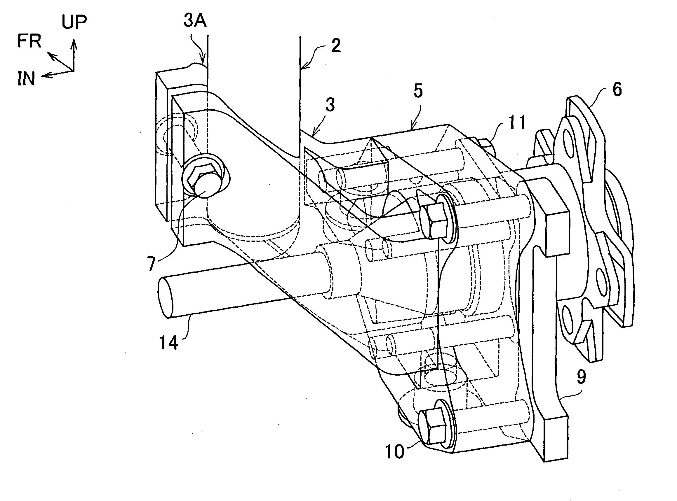
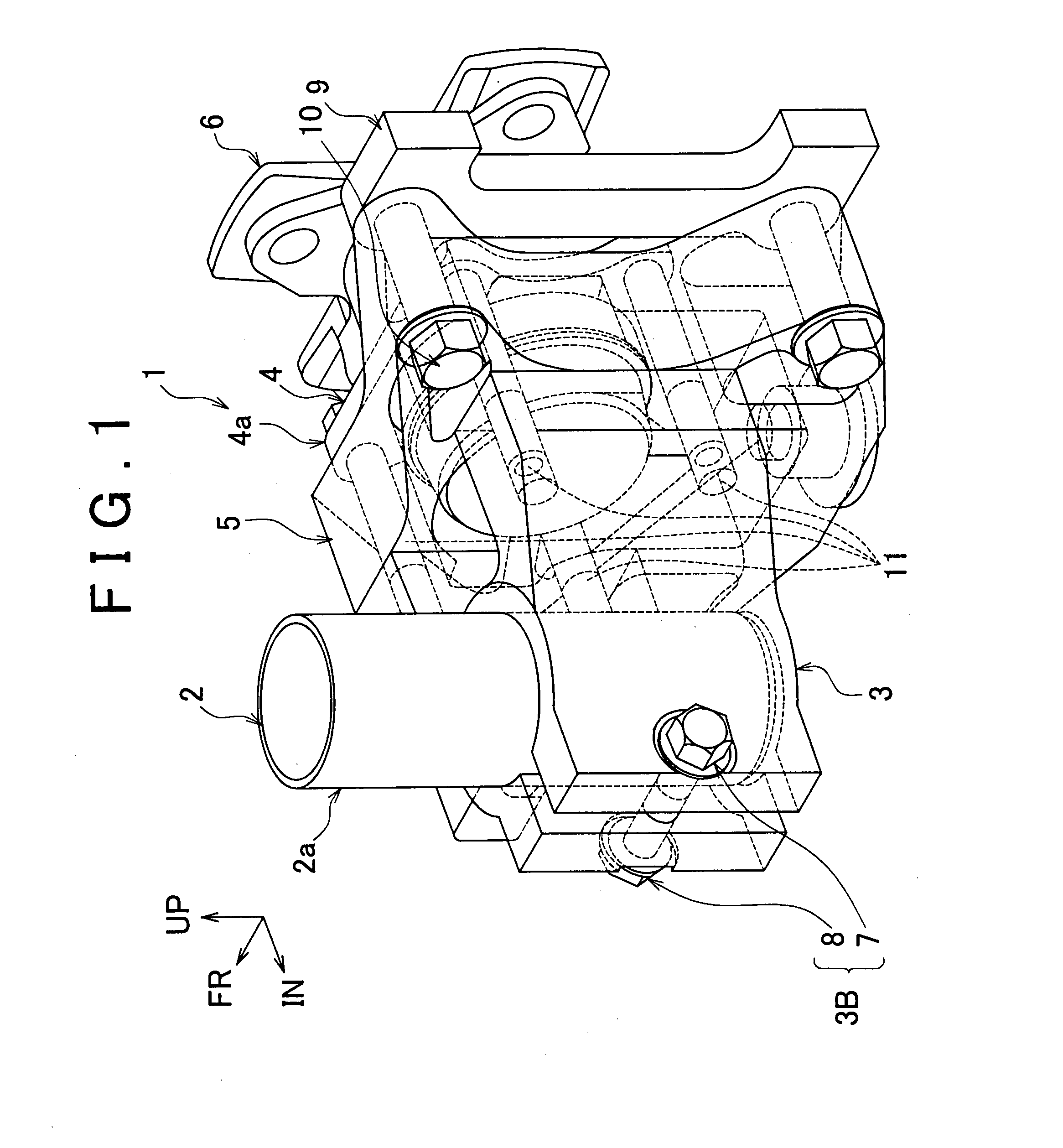
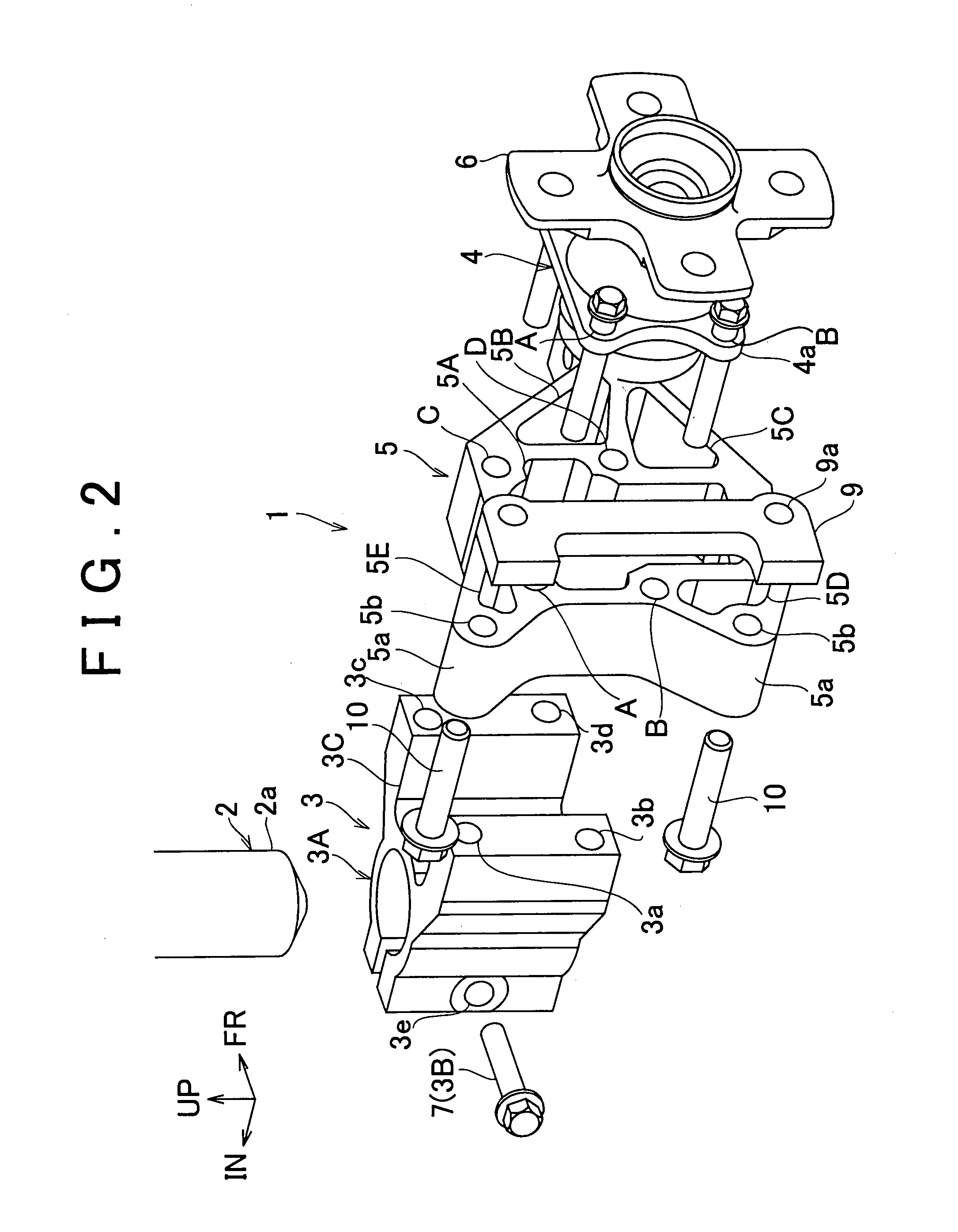
[0038]FIG. 1 is a schematic diagram showing one embodiment of a knuckle according to the invention as viewed from a position located behind a vehicle and inside with respect to a vehicle width direction. FIG. 2 is a schematic diagram showing the embodiment of the knuckle according to the invention with its components arranged side by side in the vehicle width direction as viewed from a position located behind the vehicle and outside with respect to the vehicle width direction. FIG. 3 is a schematic diagram showing the embodiment of the knuckle according to the invention as viewed from a position located inside with respect to the vehicle width direction and below. In FIGS. 1 to 3, UP, FR, and IN denote an upward direction, a forward direction with respect to the vehicle, and an inward direction with respect to the width of the vehicle, respectively.

[0039]As sh...


PUM


Abstract

The invention provides a knuckle and a method of manufacturing the knuckle that do not cause an increase in the number of man-hours. A knuckle according to the invention is equipped with a knuckle part for fixing a shock absorber constituting a suspension unit, a bearing for rotatably supporting a wheel, and a knuckle part for supporting the bearing. The knuckle part is constructed by being extruded in an axial direction of the shock absorber and the knuckle part is constructed by being extruded in an axial direction of the bearing.

Description

BACKGROUND OF THE INVENTION[0001]1. Field of the Invention[0002]The invention relates to a knuckle suited to be applied to a suspension unit for a vehicle such as a passenger car, a truck, a bus or the like.[0003]2. Description of the Related Art[0004]As suspension units applied to vehicles, suspension units of an independent suspension type that independently support left wheels and right wheels with a view to improving the grounding property of the wheels have been employed. For example, suspension units of a multi-link type, a double wishbone type, and a McPherson strut type are well known. Especially a suspension unit of the McPherson strut type is constructed such that a knuckle for rotatably supporting each wheel is coupled to a vehicle body side via a lower arm, and that an intermediate part of this lower arm or the knuckle and the vehicle body side are coupled to each other by a shock absorber. The suspension unit of the McPherson strut type is therefore simple in structure ...

Claims


Application Information

Patent Timeline
Patent Type & Authority Applications(United States)
IPC IPC(8): B62D7/18
CPCB60G13/005B60G2206/8105B60G2206/50B60G2204/129
Inventor MURATA, SATOSHI
Owner TOYOTA JIDOSHA KK
Learn More