Relay module

a relay module and relay technology, applied in the field of relay modules, can solve the problems of reducing operational reliability, relay module b>1/b> failing to detect an electric current with high accuracy, and inability to operate, so as to improve the operational reliability of the relay module, improve and improve the effect of the temperature of the detection conductor

Pending Publication Date: 2021-12-09
PANASONIC INTELLECTUAL PROPERTY MANAGEMENT CO LTD
View PDF0 Cites 0 Cited by
  • Summary
  • Abstract
  • Description
  • Claims
  • Application Information

AI Technical Summary

Benefits of technology

[0008]According to the present disclosure, the electric current detector is disposed to be thermally strongly bonded to the insulating layer and the heat dissipator and be thermally weakly bonded to the fuse. Therefore, heat that is likely to be generated at the relay, the connection point between the relay and detection conductor, and the like is actively discharged to the heat dissipator. Furthermore, heat that is likely to be generated at the relay, the connection point between the relay and the interruption conductor, and the like is not easily transferred to the detection conductor. Therefore, even if a high electric current continuously flows to the relay module, an increase in the temperature of the detection conductor due to factors other than heat generation caused by an electric current flowing to the detection conductor is suppressed. As a result, the operating temperature range of the electric current detector is properly secured, enabling accurate electric current detection of the detection conductor; thus, the operational reliability of the relay module can be improved.

Problems solved by technology

As a result, even in the state where the electric current flowing to fuse 10 has not reached an allowable electric current value, in other words, even in the normal operation range of relay module 1, the electric current sensor may become unable to operate normally, causing relay module 1 to fail in detecting an electric current with high accuracy.
This means that in conventional relay module 1, there is a possibility that the operational reliability may decrease.
Furthermore, heat that is likely to be generated at the relay, the connection point between the relay and the interruption conductor, and the like is not easily transferred to the detection conductor.

Method used


Image

  • Relay module
  • Relay module
  • Relay module

Examples


Embodiment Construction

[0019]Hereinafter, an exemplary embodiment of the present disclosure will be described with the Drawings.

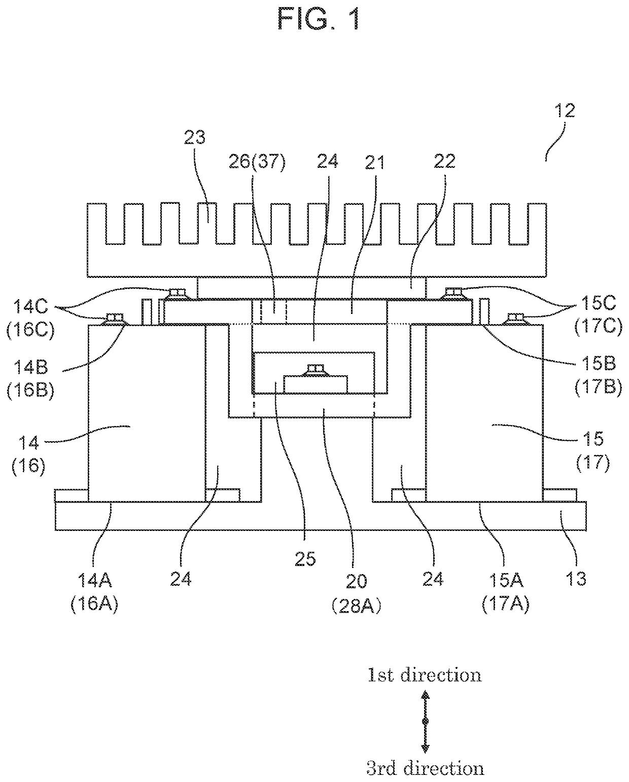
[0020]In the present exemplary embodiment, the upward direction is referred to as a first direction, the horizontal direction is referred to as a second direction, and the downward direction is referred to as a third direction.

EXEMPLARY EMBODIMENT

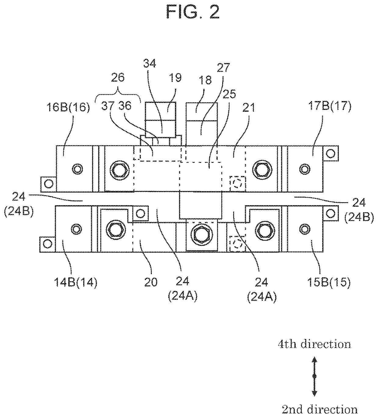
[0021]FIG. 1 is an external side view illustrating the configuration of a relay module according to an exemplary embodiment of the present disclosure. FIG. 2 is an external top view illustrating the configuration of the relay module according to the exemplary embodiment of the present disclosure.

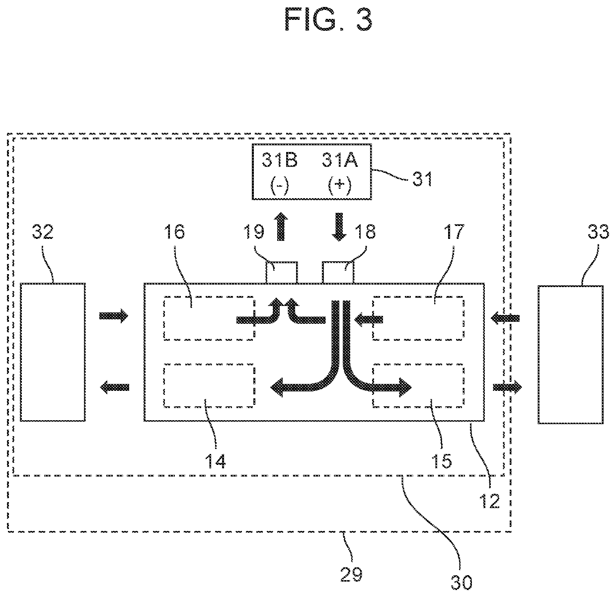
[0022]Relay module 12 includes: base 13, first load relay 14, first charging relay 15, second load relay 16, second charging relay 17, first input terminal 18, second input terminal 19, interruption conductor 20, detection conductor 21, insulating layer 22, and heat dissipator 23. In FIG. 2, for convenience of description, base 13, insulating lay...


PUM


Abstract

A fuse is at least partially located between a first load relay and a first charging relay, and an electric current detector is at least partially located between a second load relay and a second charging relay. The electric current detector is in contact with an insulating layer. As viewed from the side, the fuse is located below the electric current detector. The fuse is not in contact with the electric current detector.

Description

TECHNICAL FIELD[0001]The present disclosure relates to relay modules used in various vehicles.BACKGROUND ART[0002]Hereinafter, a conventional relay module is described with reference to a figure. FIG. 8 is an external top view illustrating the configuration of a conventional relay module. Relay module 1 includes plus-side main relay 4 and minus-side main relay 5. Plus-side main relay 4 and minus-side main relay 5 connect main battery 2 to vehicle load 3 or disconnect vehicle load 3 from main battery 2. Furthermore, relay module 1 includes plus-side charging relay 7 and minus-side charging relay 8. Plus-side charging relay 7 and minus-side charging relay 8 connect main battery 2 to external power supply 6 or disconnect external power supply 6 from main battery 2. Note that external power supply 6 charges main battery 2. Furthermore, relay module 1 includes: electric current sensor 9 that detects an electric current flowing to main battery 2; and fuse 10 that interrupts an electric cu...

Claims


Application Information

Patent Timeline
Patent Type & Authority Applications(United States)
IPC IPC(8): H01H9/10H01H89/04H01H9/02H02H1/00
CPCH01H9/10H02H1/0007H01H9/02H01H89/04H01H50/04H01H2085/025H01H2085/0291H01H85/47H01H45/00
Inventor MORI, KEISUKEWATANABE, HIDEKI
Owner PANASONIC INTELLECTUAL PROPERTY MANAGEMENT CO LTD
Why Eureka
Try Eureka