
Power converter and control method thereof

Active Publication Date: 2021-12-09
DELTA ELECTRONICS INC
View PDF26 Cites 2 Cited by
  • Summary
  • Abstract
  • Description
  • Claims
  • Application Information

AI Technical Summary

Benefits of technology

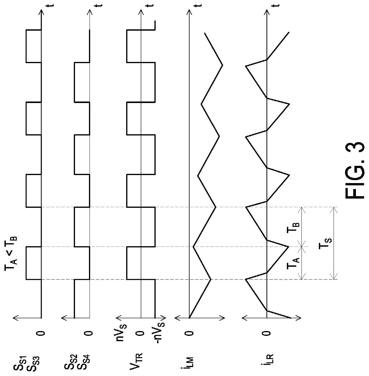
The patent text describes a power converter and control method that prevents the transformer from getting overwhelmed with power. This is achieved by enabling and disabling the switches of the converter in an alternating manner, which allows the magnetizing current to reset to zero and prevent saturation of the transformer. This method prevents the need for additional components such as blocking capacitors, sensors, and auxiliary windings.

Problems solved by technology

However, especially in high power applications, it is not practical to use the series DC blocking capacitor since it makes the converter bulky, expensive, and inefficient.
It should be noted that the uneven duty-cycles of the switches are caused by the uneven delays of the gate drive signals and / or unequal turn-on and turn-off delays of the switching devices.
However, these passive approaches are not desirable for modern power supplies since the first approach makes the transformer undesirably large whereas the second approach increases size and cost of the converter.
However, these active approaches are not desirable for cost sensitive applications since the first approach requires an additional auxiliary core with windings whereas the second approach requires two additional current sensors which increase the cost of the converter.

Method used


Image

  • Power converter and control method thereof
  • Power converter and control method thereof
  • Power converter and control method thereof

Examples


Embodiment Construction

[0020]The present disclosure will now be described more specifically with reference to the following embodiments. It is to be noted that the following descriptions of preferred embodiments of this disclosure are presented herein for purpose of illustration and description only. It is not intended to be exhaustive or to be limited to the precise form disclosed.

[0021]The present invention will now be described more specifically with reference to the following embodiments. It is to be noted that the following descriptions of preferred embodiments of this invention are presented herein for purpose of illustration and description only; it is not intended to be exhaustive or to be limited to the precise form disclosed. For example, the formation of a first feature over or on a second feature in the description that follows may include embodiments in which the first and second features are formed in direct contact, and may also include embodiments in which additional features may be formed...


PUM


Abstract

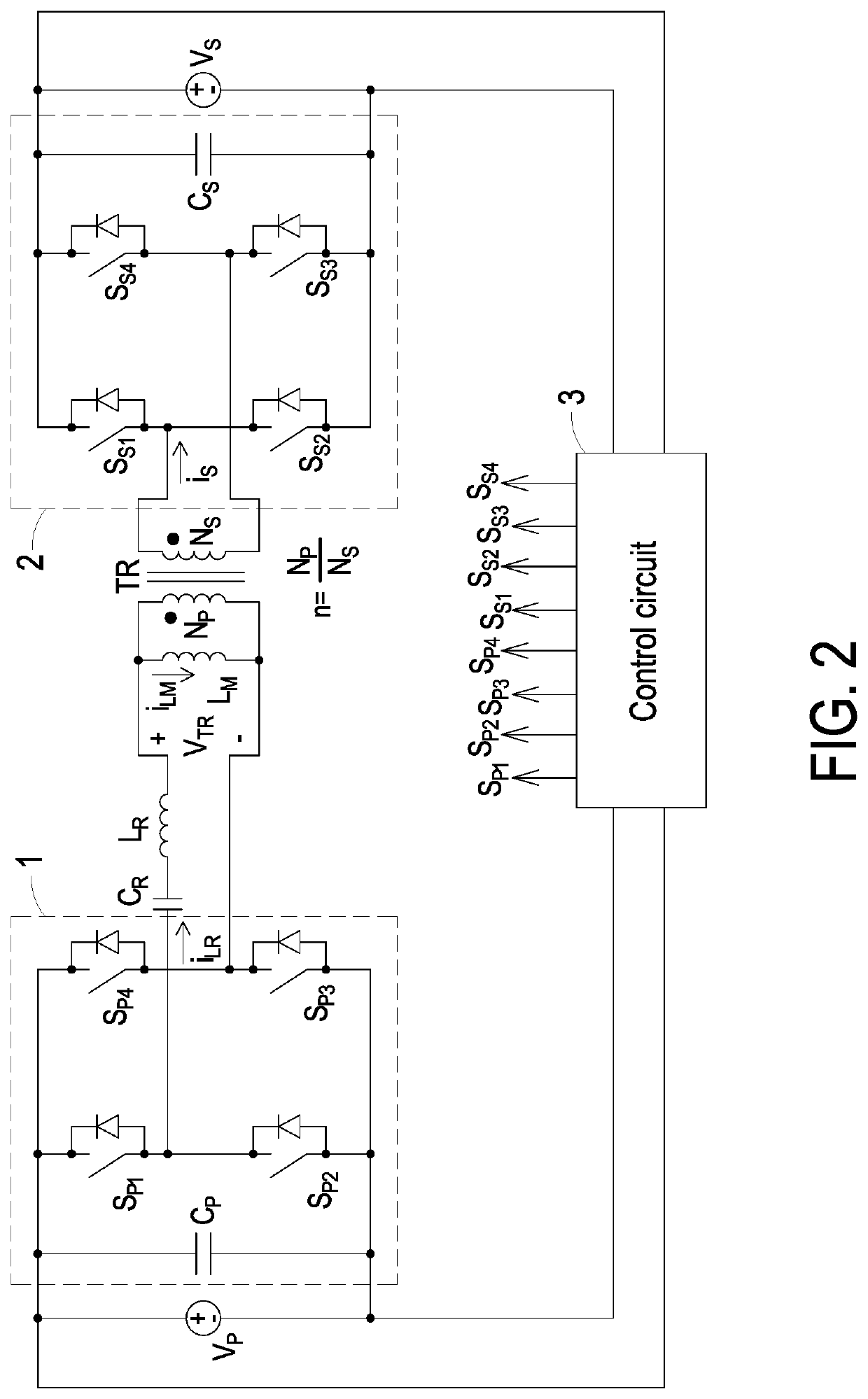
A power converter and a control method thereof are provided. The power converter includes a primary side switching circuit, a secondary side switching circuit, a transformer, and a control circuit. The primary side switching circuit includes a first set of switches. The secondary side switching circuit includes a second set of switches. The transformer is coupled between the primary side switching circuit and the secondary side switching circuit. The control circuit is configured to control power transfer between the primary side switching circuit and the secondary side switching circuit by controlling the first and second sets of switches. The control circuit is adapted to enable and disable the first and second sets of switches in an enabling duration and a disabling duration respectively and alternatively.

Description

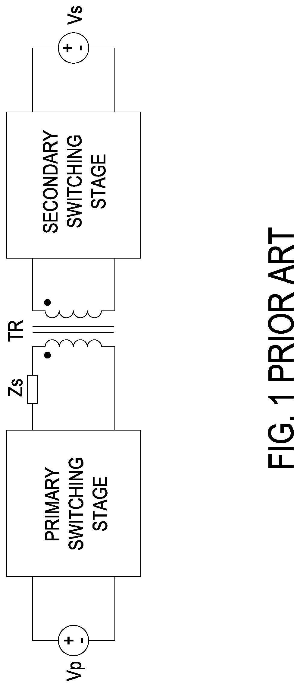
CROSS-REFERENCE TO RELATED APPLICATION[0001]This application claims the benefit of U.S. Provisional Application No. 63 / 035,145 filed on Jun. 5, 2020, entitled “ISOLATED DC / DC CONVERTER AND CONTROL METHOD THEREOF”. The entire contents of the above-mentioned patent applications are incorporated herein by reference for all purposes.FIELD OF THE INVENTION[0002]The present disclosure relates to a power converter and a control method thereof, and more particularly to a power converter and a control method thereof for preventing transformer saturation in the power converter.BACKGROUND OF THE INVENTION[0003]Nowadays, isolated DC / DC converters are widely used in many applications where a DC isolation is required between the input and output ports of the converter. To achieve the DC isolation, an isolated DC / DC converter employs a transformer that operates at the switching frequency of the converter. FIG. 1 shows a basic block diagram of a conventional isolated DC / DC converter. As shown in FI...

Claims


Application Information

Patent Timeline
IPC IPC(8): H02M3/335H02M1/32
CPCH02M3/33592H02M2001/0003H02M1/32H02M3/33584H02M3/3353H02H7/0455H02M1/40H02M1/0041Y02B70/10H02M1/0003
Inventor KUMAR, MISHAJANG, YUNGTAEK
Owner DELTA ELECTRONICS INC
Learn More