Power source circuit and switching power source

A power supply circuit and electronic switch technology, applied in the power supply field, can solve the problems of low output efficiency, easy saturation of transformers, and large variation range, and achieve the effects of improving output efficiency, increasing output power, and preventing saturation state.

Active Publication Date: 2016-05-11
ZTE CORP
View PDF5 Cites 0 Cited by
  • Summary
  • Abstract
  • Description
  • Claims
  • Application Information

AI Technical Summary

Problems solved by technology

However, when the input voltage range is very wide, the duty cycle of PWM (adjusting the pulse width modulation signal) varies greatly between the input high voltage and low voltage, which makes the transformer very easy to saturate at low voltage input, making the output efficiency relatively low. Low

Method used


Image

  • Power source circuit and switching power source
  • Power source circuit and switching power source

Examples


Embodiment Construction

[0026] It should be understood that the specific embodiments described here are only used to explain the present invention, not to limit the present invention.

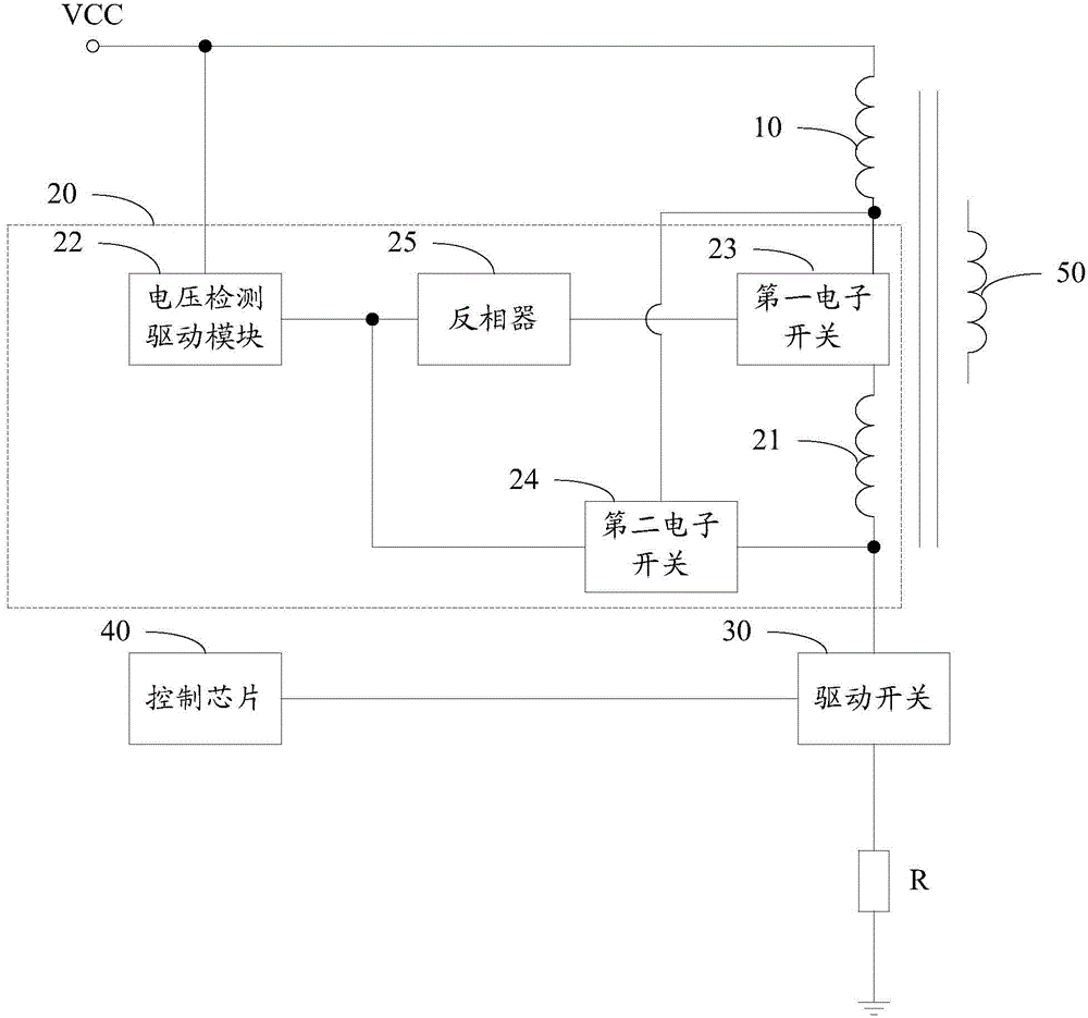
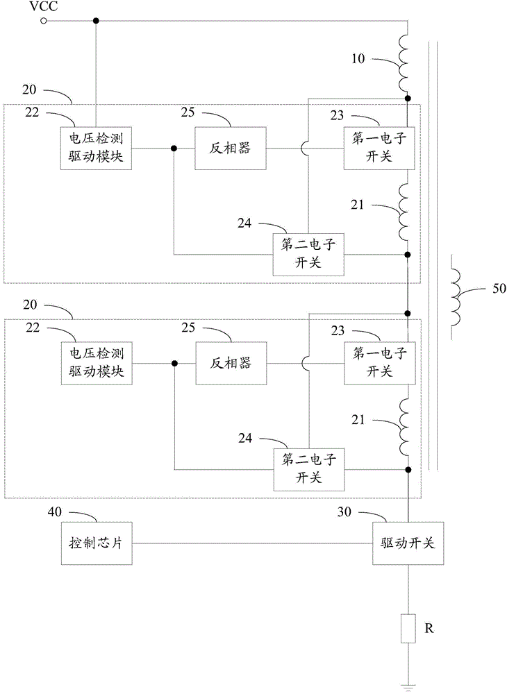
[0027] The invention provides a power supply circuit, referring to figure 1 , in one embodiment, the power supply circuit includes a first primary winding 10, at least one transformer unit 20, a drive switch 30 for controlling charge and discharge of the first primary winding 10 and a drive switch 30 for outputting pulse width The modulation signal drives the control chip 40 that drives the drive switch 30 to turn on or off; wherein,

[0028] The first end of the first primary winding 10 is electrically connected to the power supply positive input terminal VCC, and the second end of the first primary winding 10 is electrically connected to the driving switch 30 through the transformation unit 20;

[0029] The transformation unit 20 includes a second primary winding 21 and a voltage detection drive module 22 for detec...


PUM


Abstract

The invention discloses a power source circuit. The power source circuit includes a first primary side winding, at least one transformation unit, a driving switch used for performing charge and discharge control on the first primary side winding, and a control chip which is used for outputting pulse-width modulation signals to drive the driving switch to be switched on or switched off; the first end of the first primary side winding is electrically connected with a power source positive input end; the second end of the first primary side winding is electrically connected with the driving switch through the transformation units; and the transformation unit includes a second primary side winding and a voltage detection driving module which is used for detecting the voltage of the power source positive input end, wherein the voltage detection driving module controls a corresponding second primary side winding to be electrically connected with the first primary side winding according to the voltage of the power source positive input end so as to control the turns ratio of a primary coil and a secondary coil. The invention also discloses a switching power source. With the power source circuit and the switching power source of the invention adopted, the primary side coils of the transformers can be prevented from entering saturated states, and the output efficiency of the power source can be improved.

Description

technical field [0001] The invention relates to the technical field of power supply, in particular to a power supply circuit and a switching power supply. Background technique [0002] As we all know, with the rapid development of informatization, people are increasingly dependent on electronic equipment and products, and these electronic equipment and products are inseparable from power sources. With the complexity of various application environments, the power supply is required to have strong adaptability, the most important of which is to be applicable to various input voltage conditions. [0003] In order to realize a wide range of input voltages, two-stage voltage conversion is usually used in the power supply circuit in the prior art, and a step-up module or a step-down module is used to connect isolation modules in series. However, when the input voltage range is very wide, the duty cycle of PWM (adjusting the pulse width modulation signal) varies greatly between th...

Claims


Application Information

Patent Timeline
IPC IPC(8): H02M1/40H02P13/06
CPCH02M1/40
Inventor 李博杜鹏唐光明
Owner ZTE CORP
Why Eureka
Try Eureka