
Reception apparatus and reception method

a reception apparatus and a technology of a reception device, applied in the field of reception apparatus and a reception method, can solve the problems of interference with adjacent cells, unnecessary power radiation to the cell, interference with adjacent cells covered by adjacent base transceiver stations, etc., to prevent saturation and sensitivity degradation of the reception apparatus, and calibrate the offset voltage without increasing current consumption

Inactive Publication Date: 2011-03-15
PANASONIC CORP
View PDF20 Cites 5 Cited by
  • Summary
  • Abstract
  • Description
  • Claims
  • Application Information

AI Technical Summary

Benefits of technology

"The present invention relates to a reception apparatus and a reception method for use in a system where transmit power control is applied. The technical effect of the invention is to improve the efficiency of utilizing frequency channels and improve downlink speed from the base transceiver station to the mobile station by allocating time slots to each mobile station in a data frame. The invention also addresses the issue of interference between cells caused by the same frequency channels being shared by multiple mobile stations in a cell. The invention proposes a method for controlling transmit power based on the distance between the mobile station and the base transceiver station, which reduces unnecessary power and interference with adjacent cells."

Problems solved by technology

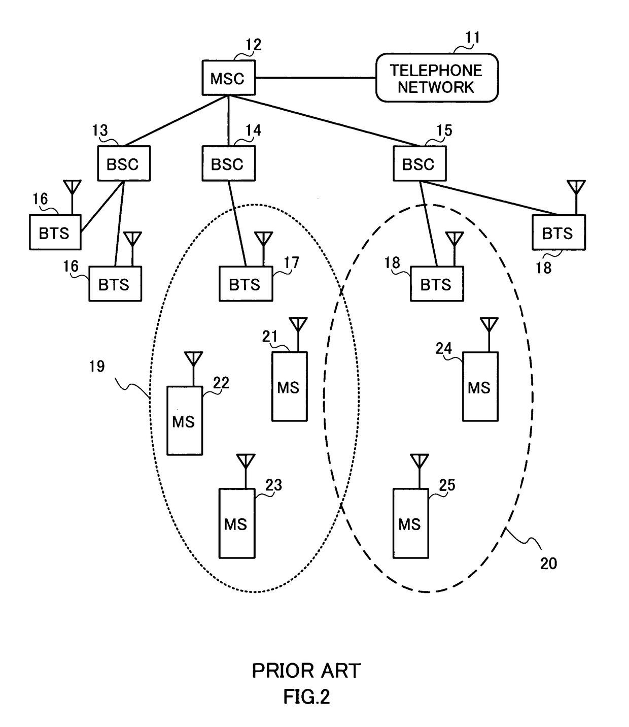
In this case, unnecessary power is radiated to the cell and interference with cells covered by adjacent base transceiver stations becomes a problem.
When transmission is performed to all the mobile stations with the same output power when the distances between mobile stations 21, 22, 23 in cell 19 and base transceiver station 17 differ from one another, transmit power is set based on the farthest mobile station, and therefore power which would be unnecessary under normal conditions is sent to the same frequency channels, which results in a problem of interference against adjacent cells.

Method used


Image

  • Reception apparatus and reception method
  • Reception apparatus and reception method
  • Reception apparatus and reception method

Examples


embodiment 1

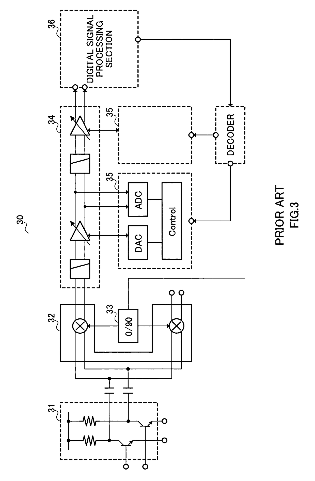
[0040]FIG. 5 is a block diagram showing the configuration of reception apparatus 100 according to Embodiment 1 of the present invention. Reception apparatus 100 according to this Embodiment 1 is a direct conversion reception apparatus.

[0041]Low noise amplifier 101 amplifies a received signal and outputs the result to quadrature demodulator 103 via capacitor 102 that removes the DC component.

[0042]Quadrature demodulator 103 has mixer 103a and mixer 103b, converts the frequency of the received signal inputted from capacitor 102 from a radio frequency to a baseband, outputs the baseband from mixer 103a to analog baseband circuit 105a and at the same time outputs the baseband from mixer 103b to analog baseband circuit 105b.

[0043]Phase shifter 104 generates two signals which have a phase difference of 90 degrees mutually from a local oscillation signal inputted from a local oscillation source (not shown) and outputs the two signals to mixer 103a and mixer 103b of quadrature demodulator ...

embodiment 2

[0083]FIG. 12 shows a time slot of a received signal in GPRS received by the reception apparatus of this Embodiment 2. The reception apparatus in this Embodiment 2 has the same configuration as that in FIG. 5 and detailed explanations thereof will be omitted.

[0084]In FIG. 12, the time slot of the received signal in GPRS is composed of header field 801 and data field 802.

[0085]Next, the operation of the reception apparatus will be explained using FIG. 5 and FIG. 7. In GPRS, there is a possibility that power control may be realized using a P0 parameter in the control channel and PR parameter in header field 801 in the corresponding time slot. According to the GSM specification “Digital cellular telecommunications system (Phase 2+); Radio subsystem link control (3GPP TS 05.08 ver 8.16.0 Release 1999)”, a mobile station reception apparatus is required to satisfy the GSM specification “Digital cellular telecommunications system (Phase 2+); Radio transmission and reception (3GPP TS 05.05 ...

embodiment 3

[0089]FIG. 13 is a block diagram showing the configuration of reception apparatus 1300 according to Embodiment 3 of the present invention. Reception apparatus 1300 according to this Embodiment 3 is a direct conversion reception apparatus and adds comparison section 1301 as shown in FIG. 13 to reception apparatus 100 according to Embodiment 1 shown in FIG. 5. Parts in FIG. 13 having the same configuration as those in FIG. 5 are assigned the same reference numerals and explanations thereof will be omitted.

[0090]Field intensity measurement section 108 reduces the influence of fading from the measurement result of RSSI inputted from digital signal processing section 106 using a publicly known method, obtains the received signal level of BCCH which becomes control reference of base transceiver station transmit power for each time slot and outputs the obtained BCCH level information to gain setting section 109. Furthermore, when information of the time slot to be excluded, which is inform...


PUM


Abstract

A reception apparatus capable of preventing saturation and sensitivity degradation of a receiver when base transceiver station transmit power control is performed and calibrating offset voltage without increasing the amount of current consumption. In this apparatus, a gain setting section (109) estimates reception field intensity of each time slot in the next frame based on information of the reception field intensity and transmit power information which is information of the transmit power of the base transceiver station and calculates a gain set value according to the estimated reception field intensity. A gain control circuit (110) extracts a maximum gain out of the gains set by the gain setting section (109), uses the maximum gain as a set gain for DC offset voltage calibration and performs gain control at the gain set value corresponding to each time slot. A voltage calibration circuit (111) performs the DC offset voltage calibration of the received signal.

Description

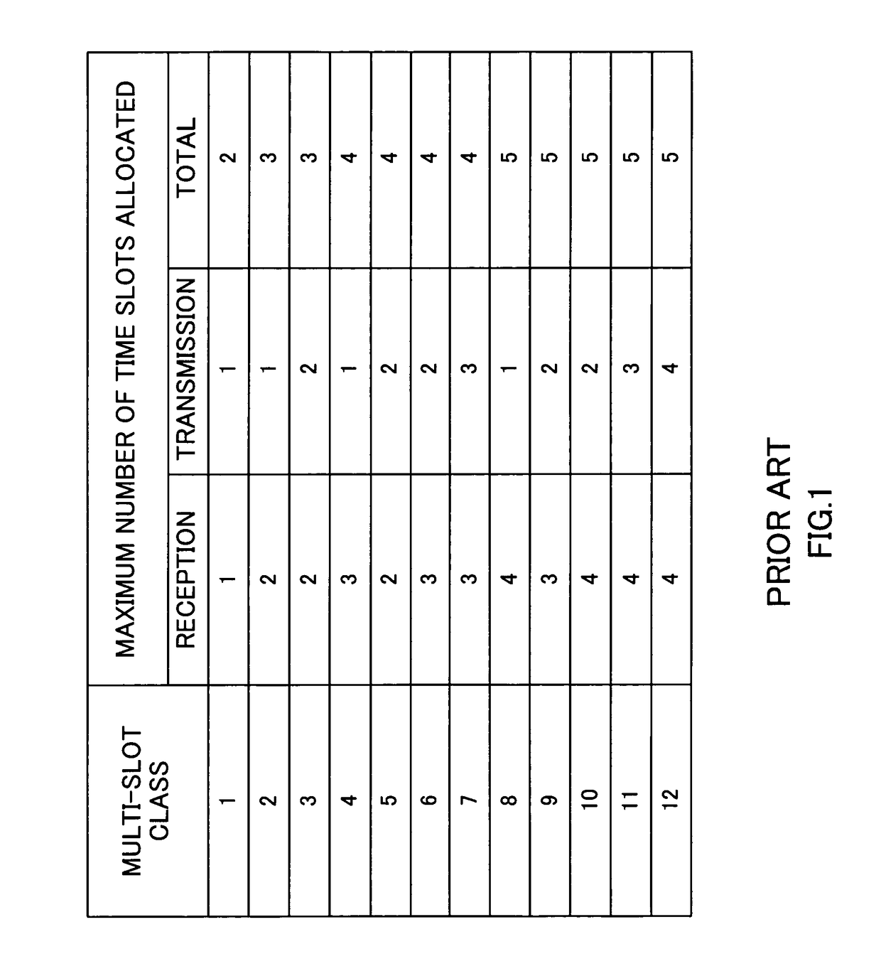
TECHNICAL FIELD[0001]The present invention relates to a reception apparatus and a reception method, and more particularly, to a reception apparatus and a reception method for use in a system where transmit power of transmission signals varies by downlink transmit power control.BACKGROUND ART[0002]In cellular phone services in recent years, in addition to voice calls, a demand for data communication is expanding with an increasing number of subscribers (mobile stations), and therefore it is important to efficiently use resources such as frequency channels and improve communication speed. For example, in a GSM (Global System for Mobile communications) system which is becoming popular mainly in Europe and Asian regions, services corresponding to high-speed communication called “GPRS” (General Packet Radio Service) have started. In GPRS, with respect to a link between mobile stations and a base transceiver station, instead of allocating dedicated frequency channels to a specific mobile ...

Claims


Application Information

Patent Timeline
Patent Type & Authority Patents(United States)
IPC IPC(8): H04J3/00H04B1/04H04B1/06H04L27/08H03G3/30H04B7/005
CPCH03G3/3052H04W52/143H04W52/10H04W52/08
Inventor SHIMIZU, YOSHITOSAITO, NORIAKI
Owner PANASONIC CORP
Learn More