Vehicle control device

Pending Publication Date: 2021-12-16
HITACHI ASTEMO LTD
View PDF0 Cites 1 Cited by
  • Summary
  • Abstract
  • Description
  • Claims
  • Application Information

AI Technical Summary

Benefits of technology

The present invention aims to enhance the safety and operability of automatic parking by reducing the intervention of the driver during the operation.

Problems solved by technology

However, the travelable region is determined by the control device based on the position information, and it may give a sense of discomfort when it does not match the driver's sensibility (for example, the speed when passing near an obstacle is high).

Method used


Image

  • Vehicle control device
  • Vehicle control device
  • Vehicle control device

Examples


example 1

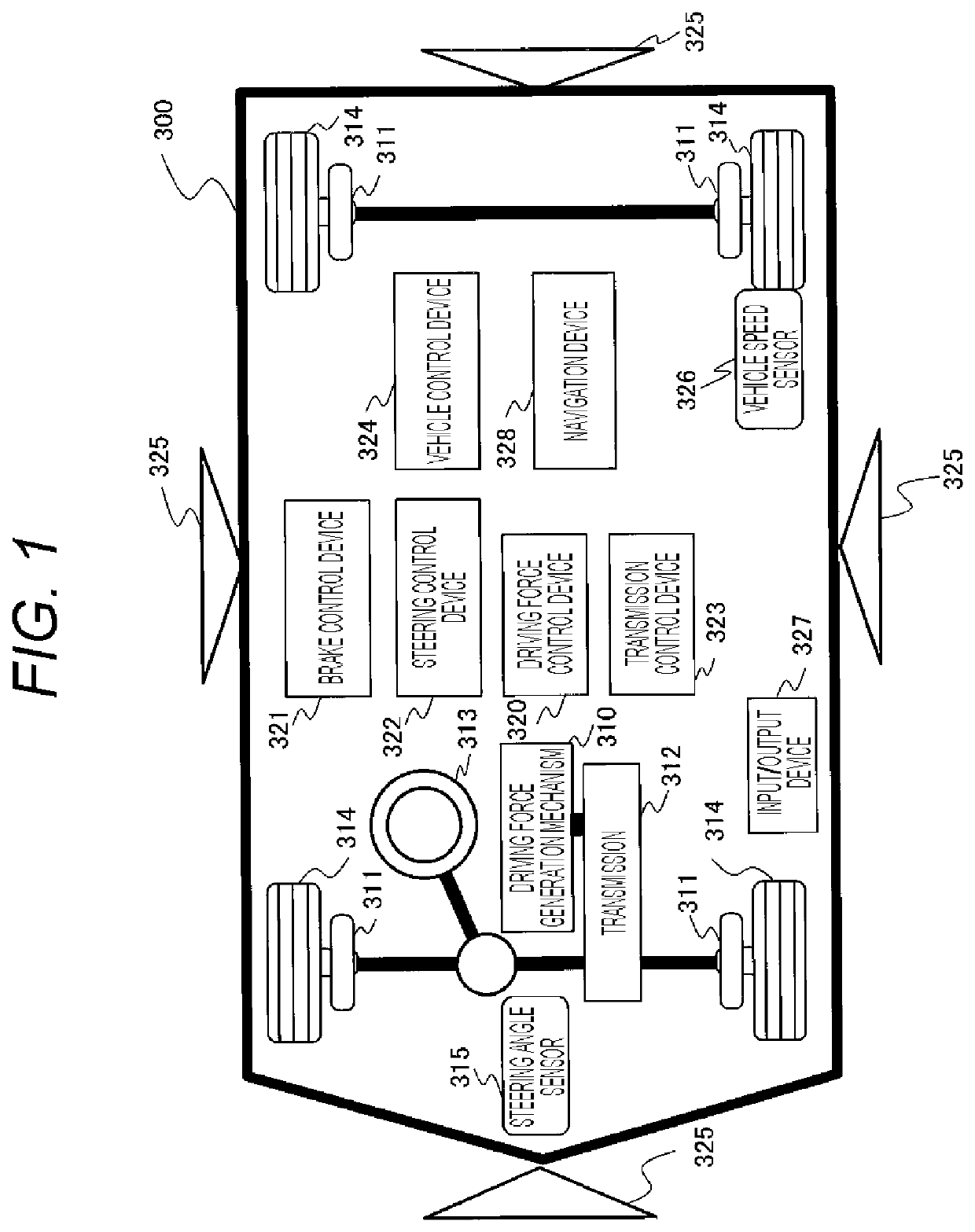
[0040]FIG. 1 is a block diagram showing a configuration of a vehicle including a vehicle control device 324 according to Example 1 of the present invention.

[0041]A vehicle 300 includes a driving force generation mechanism 310, which is a power source, a brake 311 that brakes the vehicle, and a transmission 312 having a transmission mechanism that switches the driving force generated by the driving force generation mechanism 310 in an appropriate direction and moves the vehicle forward or backward. The output of the transmission 312 rotates the left and right wheels 314 to drive the vehicle 300, and the brake 311 is controlled to generate a braking force to decelerate the vehicle 300.

[0042]The driving force generation mechanism 310 may be an engine, a hybrid mechanism of an engine and a motor, or a single motor. The vehicle 300 includes a steering wheel 313, and by operating the steering wheel 313, the steering angle of the wheels 314 is changed, and the vehicle 300 turns.

[0043]A con...

example 2

[0151]Example 2 shows an example of the setting process of the travelable region 706 based on the driver operation intervention information 450 in step 505 shown in Example 1. FIG. 12 is a flowchart showing an example of the travelable region setting process based on the driver operation intervention information. This process is performed in place of FIG. 6 of Example 1. FIG. 13 is a plan view showing an example of the set travel route. The other configurations are the same as those in Example 1.

[0152]In FIG. 12, in step S801, as in Example 1, the route generation unit 403 selects the line segment of the travelable region 104 to be changed based on the position and the angle of the vehicle 300 at which the intervention by the driver in the driving operation occurs, and the traveling direction before the driver intervenes in the operation.

[0153]In step S802, the route generation unit 403 sets a predetermined distance r (radius r) from each vehicle endpoint 704 as in Example 1.

[0154]I...

example 3

[0168]Example 3 shows an example of the setting process of the travelable region 706 based on the driver operation intervention information 450 in step 505 shown in Example 1. FIG. 14 is a flowchart showing an example of the travelable region setting process based on the driver operation intervention information. This process is performed in place of FIG. 6 of Example 1. FIG. 15 is a plan view showing an example of the set travel route. The process of steps S801 to S804 is the same as that of FIG. 6 of Example 1. The other configurations are the same as those in Example 1.

[0169]As described in Example 2, the route generation unit 403 may determine whether to permit the resetting of the travelable region 706 based on the driver operation intervention information 450 based on comparison of vehicle state information of the traveling history information 460 during automatic parking. In other words, the route generation unit 403 changes the position only for the line segment satisfying a...


PUM


Abstract

A vehicle control device, which reduces intervention in automatic parking by a driver, includes a processor and a memory, that control the vehicle to a target parking position. The vehicle control device includes an obstacle detection unit detecting a position of an obstacle around the vehicle, a travelable region setting unit that determines a region where the vehicle may travel based on the position of the obstacle, and sets the target parking position within the travelable region, a route generation unit that calculates a travel route to the target parking position within the travelable region, and an automatic parking execution unit that causes the vehicle to automatically travel toward the target parking position. When a driver intervenes during the automatic traveling, the route generation unit stores vehicle state information at the time of the intervention, and resets the travelable region based on the driver operation intervention information.

Description

Technical Field[0001]The present invention relates to a vehicle control device that assists in parking a vehicle.BACKGROUND ART[0002]Advanced drive assistance systems have been developed to prevent traffic accidents and reduce the driving load on a driver during traffic jams. One of the advanced drive assistance systems includes is automatic parking. In automatic parking, when the driver specifies a target parking position, the vehicle control device automatically performs some or all of the accelerator, brake, and steering operations to park the vehicle.[0003]A vehicle that provides automatic parking includes sensing devices such as a camera and an ultrasonic sensor that grasp the surrounding environment of the vehicle, and the control device calculates the travelable region based on the position information (sensor information) of an obstacle (parked vehicle, and the like) acquired from the sensing device. Next, the control device calculates the turning position and the like based...

Claims


Application Information

Patent Timeline
IPC IPC(8): B60W30/06B60W50/00B60W50/10B60W10/20B60W10/18B60W10/04B60W10/10
CPCB60W30/06B60W50/0098B60W50/10B60W10/20B60W10/18B60W10/04B60W2720/125B60W2556/10B60W2710/1005B60W2710/18B60W2710/20B60W2720/106B60W10/10B62D15/0285
Inventor TASHIRO, NAOYUKISEIMIYA, MASASHIMATSUDA, SATOSHIIMAI, MASATO
Owner HITACHI ASTEMO LTD
Why Eureka
Try Eureka