Solenoid valve

a solenoid valve and valve body technology, applied in the direction of valve housings, magnetic bodies, operating means/releasing devices, etc., can solve the problems of high manufacturing cost, high degree of forming technology, and high manufacturing cost, so as to reduce the magnetic efficiency, reduce the springback of metal plates, and stabilize the box shape

Active Publication Date: 2021-12-23
SMC CORP
View PDF0 Cites 2 Cited by
  • Summary
  • Abstract
  • Description
  • Claims
  • Application Information

AI Technical Summary

Benefits of technology

[0023]According to the present invention, even if a magnetic cover is formed by bending a metal plate, a joint of the metal plate can be reliably prevented from opening so as to form a gap by suppressing springback of the metal plate. As a result, a stable box shape can be maintained, and a decrease in the magnetic efficiency due to an increase in the magnetic reluctance can be prevented.

Problems solved by technology

However, this method requires a high degree of forming technology and high manufacturing costs.
However, a magnetic cover formed by bending a metal plate has a joint portion of the metal plate, and thus, there is a problem in that a gap is likely to be formed at the joint portion due to springback of the bent metal plate.
If a gap is formed at the joint portion, the shape of the magnetic cover becomes unstable, which adversely affects the assembly of the solenoid valve.
In addition, there is a possibility that the magnetic reluctance may increase and that the magnetic efficiency may decrease.

Method used


Image

  • Solenoid valve
  • Solenoid valve
  • Solenoid valve

Examples


Embodiment Construction

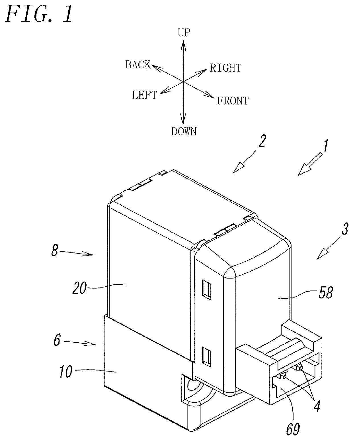
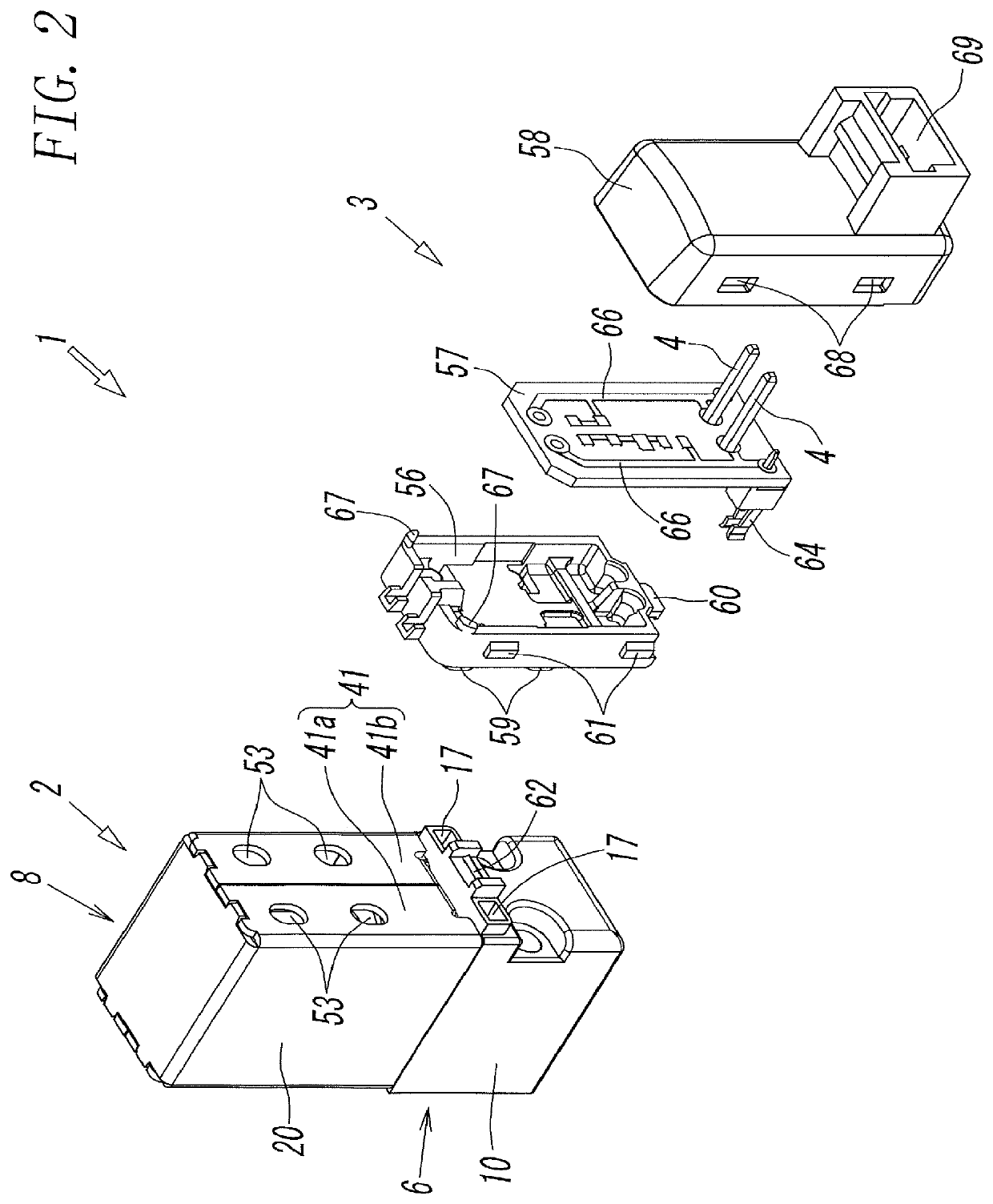
[0033]FIG. 1 is a perspective view of a solenoid valve according to the present invention, and as illustrated in FIG. 2, a solenoid valve 1 includes a solenoid-valve main body 2 and an electric connecting unit 3 that includes a pair of connection terminals 4 and 4 to which a lead wire extending from a control device is connected.

[0034]Note that, in the following description, frontward and rearward directions, leftward and rightward directions, and upward and downward directions of the solenoid valve 1 are defined as the directions indicated by arrows in FIG. 1.

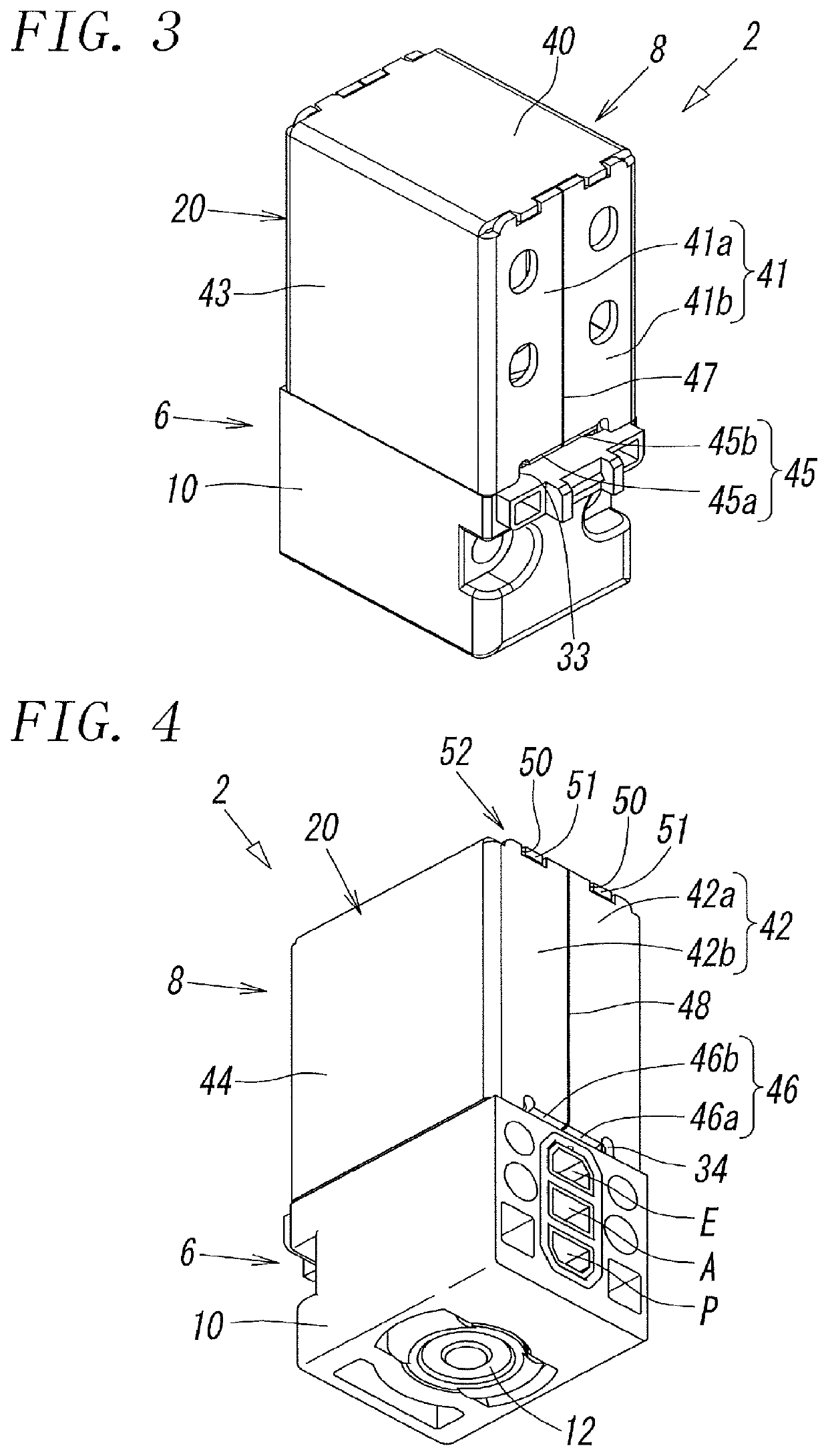
[0035]As illustrated in FIG. 3 to FIG. 6, the solenoid-valve main body 2 includes a main valve unit 6 that includes a valve member 7 movable to open and close a flow path and an electromagnetic operation unit 8 that causes, by using an electromagnetic force, the valve member 7 to perform opening and closing operations, and the electromagnetic operation unit 8 and the main valve unit 6 are coupled to each other along an axis L....


PUM

PropertyMeasurementUnit
electromagnetic forceaaaaaaaaaa
shapeaaaaaaaaaa
depthaaaaaaaaaa

Abstract

Latch protrusions of an upper surface wall are latched into latch recesses of a first front-surface half wall and an upper end portion of a second front-surface half wall of a magnetic cover, and latch protrusions of the upper surface wall are latched into latch recesses of a first rear-surface half wall and an upper end portion of a second rear-surface half wall of the magnetic cover. Hook portions of the first front-surface half wall and a lower end portion of the second front-surface half wall are folded into a coupling groove of the valve body, and hook portions of the first rear-surface half wall and a lower end portion of the second rear-surface half wall are folded into a coupling groove of the valve body.

Description

TECHNICAL FIELD[0001]The present invention relates to a solenoid valve that includes a main valve unit and an electromagnetic operation unit, and more particularly, to a solenoid valve in which the electromagnetic operation unit is covered with a magnetic cover.BACKGROUND ART[0002]A solenoid valve that includes a main valve unit and an electromagnetic operation unit is commonly known as described in PTL 1 to PTL 5. In this type of solenoid valve, the main valve unit includes a valve body having a plurality of ports and a valve member that opens and closes a flow path connecting the ports, and the electromagnetic operation unit is formed by arranging, in a magnetic cover having a quadrangular box shape, an electromagnetic coil, a stationary core that generates a magnetic force as a result of the electromagnetic coil being energized, and a movable core that causes, by being attracted to the stationary core and separated from the stationary core, the valve member to perform opening and...

Claims


Application Information

Patent Timeline
Patent Type & Authority Applications(United States)
IPC IPC(8): F16K31/06H01F7/08
CPCF16K31/0675H01F7/081H01F2007/083H01F7/127F16K31/0624F16K27/003F16K27/029F16K31/06H01F7/16
Inventor MITA, MINEHIKOMORIMOTO, MASAKI
Owner SMC CORP
Why Eureka
Try Eureka