Manufacturing method of stamped part, press forming device, and metal plate for press forming

A manufacturing method and stamping forming technology, applied in the field of stamping parts manufacturing, can solve the problems of large change in cross-section and limited application range of stamping and forming, etc.

Active Publication Date: 2022-04-29
JFE STEEL CORP
View PDF7 Cites 0 Cited by
  • Summary
  • Abstract
  • Description
  • Claims
  • Application Information

AI Technical Summary

Problems solved by technology

[0007] However, in Patent Document 1, it is necessary to provide a step shape in the vertical wall portion, so the cross-section of the target punched part shape may be greatly changed, and there is a limit to the application range of press forming.

Method used


Image

  • Manufacturing method of stamped part, press forming device, and metal plate for press forming
  • Manufacturing method of stamped part, press forming device, and metal plate for press forming
  • Manufacturing method of stamped part, press forming device, and metal plate for press forming

Examples


Embodiment

[0094] Next, an example of this embodiment will be described.

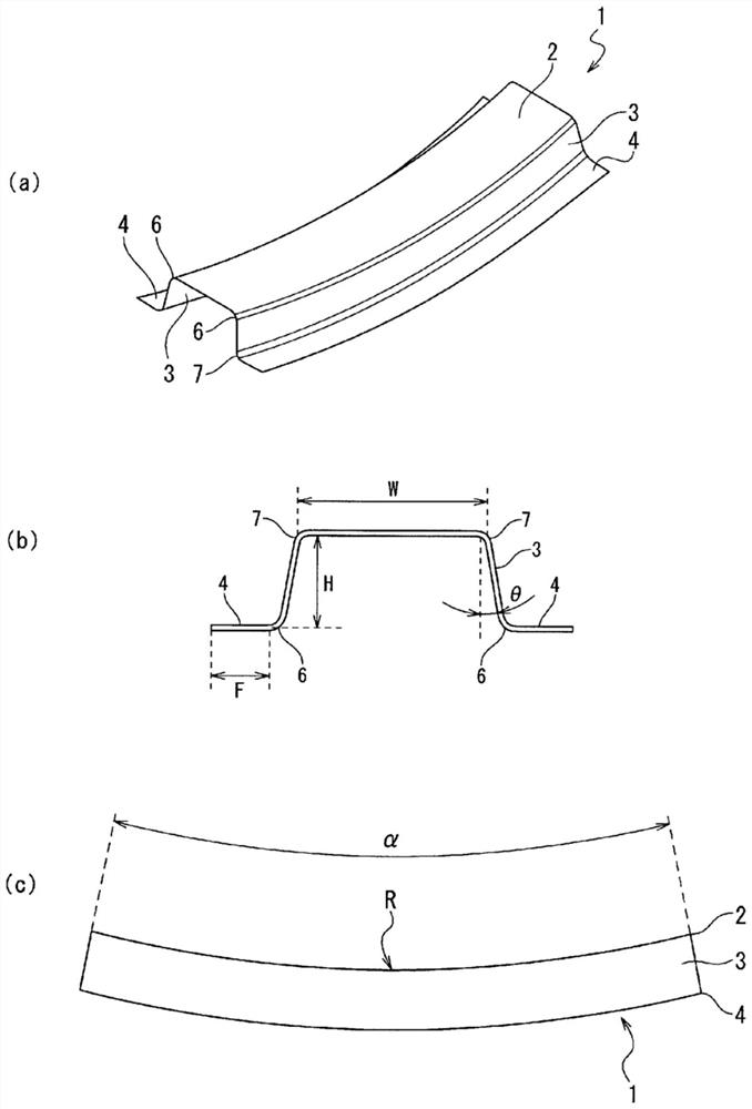
[0095] Suppose it is a 1180MPa grade cold-rolled steel sheet (thickness of 1.4mm), and it has the following characteristics Figure 1 The components with the shape shown above are analyzed by press molding.

[0096] In this embodiment, the shape parameters that define the shape 1 of the punched part are set as follows.

[0097]

[0098] Width of top plate w: 100mm

[0099] Longitudinal wall height h: 50mm

[0100] Longitudinal wall angle θ: 10 degrees

[0101] The flange length f: 30mm

[0102]

[0103] Bending angle α: 30 degrees

[0104] Roof curvature radius r: 1000mm

[0105] The length of the metal plate 10 for molding is set to be equal to the length of the top plate 2 of the target stamping part shape 1. Specifically, based on the above formula (1), the length of the metal plate 10 in the longitudinal direction is 523.6 mm.. In addition, the width was set to about 260mm.

[0106] Next, the length of the flange...


PUM

PropertyMeasurementUnit
tensile strengthaaaaaaaaaa
lengthaaaaaaaaaa

Abstract

The present invention provides a press-forming technology capable of reducing molding defects of a molded part having a curved shape protruding toward a flange side when viewed from the side. This technique includes: a first forming step (9A) of press-forming a metal plate (10) into an intermediate molded product (40) having an undulating shape at a vertical wall portion forming position (13) and a flange portion forming position (14), The undulating shape has a concavo-convex shape continuous along the longitudinal direction, and the amplitude of the concavo-convex shape in the plate thickness direction gradually increases toward the position corresponding to the boundary between the vertical wall portion (3) and the flange portion (4); In the second forming step (9B), bending is performed on the intermediate formed product (40). The line length in the longitudinal direction at the position corresponding to the boundary between the vertical wall portion (3) and the flange portion (4) in the intermediate molded product (40), and the distance between the vertical wall portion (3) and the flange portion (4) in the stamped part shape (1). Line lengths in the longitudinal direction of the boundaries of the flange portion (4) are identical or close to each other.

Description

Technical field [0001] The present invention relates to a technology for manufacturing a stamped part with a hat-shaped cross-section shape, which has at least one bent part protruding to the flange part side (recessed to the top plate part side) along the long side direction when viewed from the side. The present invention is a technology particularly suitable for the manufacture of automobile frame parts with parts bent toward the top plate side when viewed from the side. technical background [0002] For example, an automobile frame member has a top plate, a vertical wall and a flange which are continuous in the left and right width directions of the top plate, and has a shape with a bent part bent in the long side direction when viewed from the side. In the case of manufacturing such automobile frame parts from flat metal plates by press molding, cracks and wrinkles may occur in a part of the parts, resulting in poor molding. In addition, there is a concern that the molded pr...

Claims


Application Information

Patent Timeline
Patent Type & Authority Patents(China)
IPC IPC(8): B21D22/26B21D19/08B21D22/02B21D22/20B21D24/00
CPCB21D22/02B21D22/20B21D53/88B21D19/08B21D22/26B21D24/00
Inventor 三宅弘人新宫丰久山崎雄司
Owner JFE STEEL CORP
Why Eureka
Try Eureka