

Reactor design to reduce particle deposition during process abatement
a technology of process abatement and reactor design, applied in the field of improved, can solve the problems of halogens, e.g., fluorine (fsub>2/sub>), and other fluorinated compounds, and achieve the effect of reducing the accumulation of particulate products and reducing the cracking of the reactor chamber
Inactive Publication Date: 2007-11-29
APPLIED MATERIALS INC
View PDF99 Cites 79 Cited by
- Summary
- Abstract
- Description
- Claims
- Application Information
AI Technical Summary
Benefits of technology
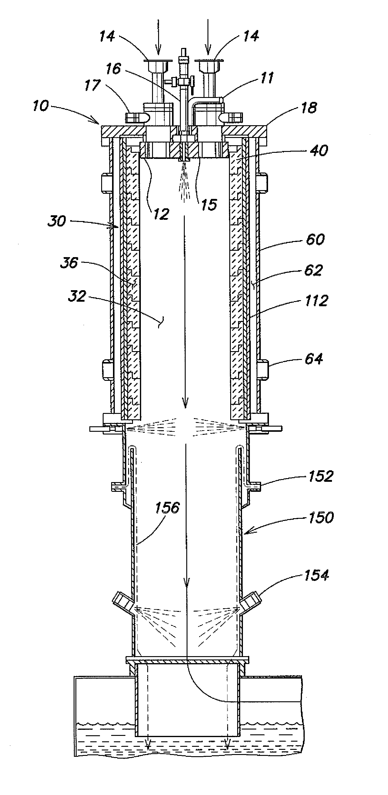
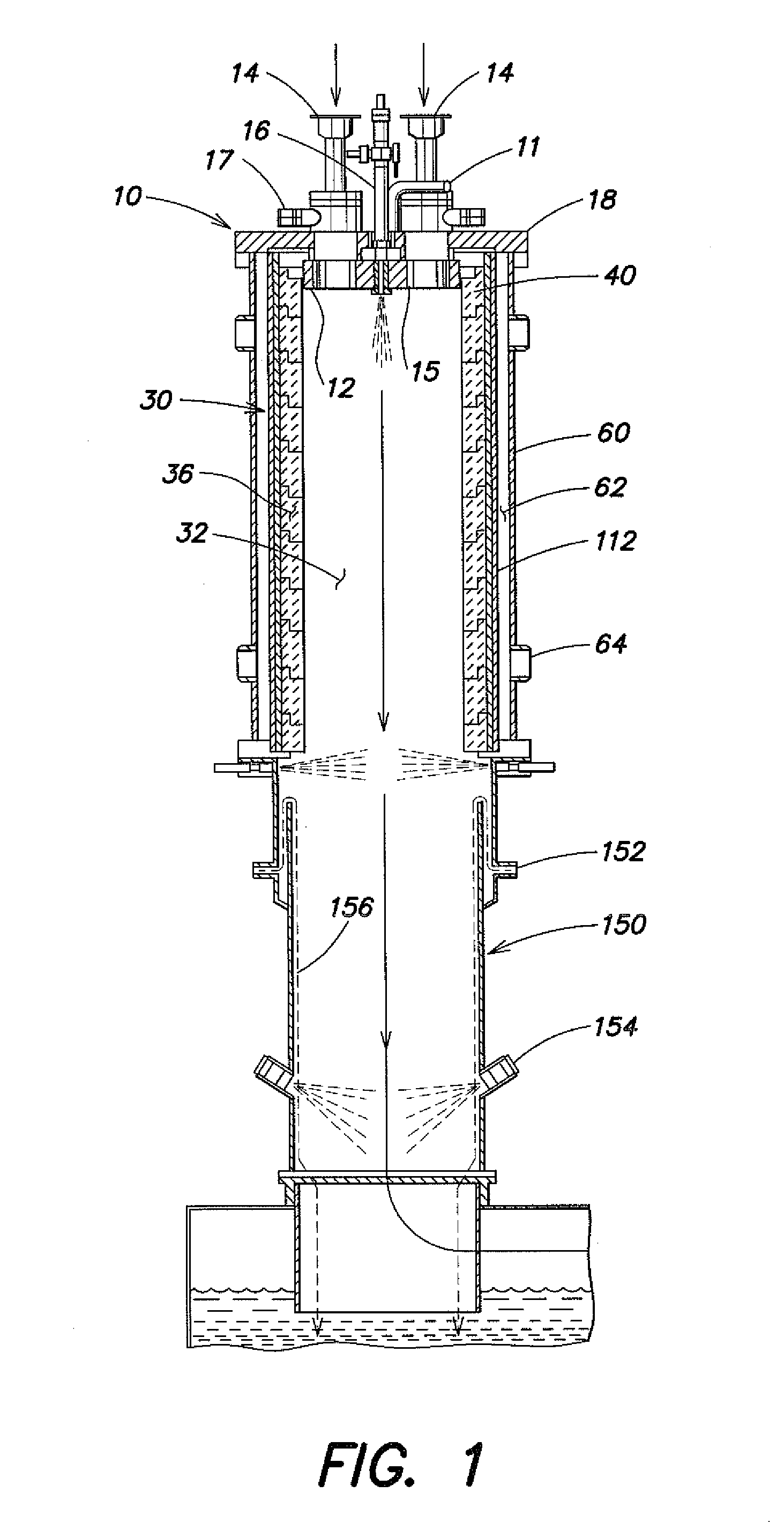
The present invention relates to methods and systems for controlled decomposition of gaseous liquid crystal display (LCD) and semiconductor wastes in a thermal reactor while reducing accumulation of the particulate products of the decomposition within the system. The invention also includes an improved thermal reactor design to reduce reactor chamber cracking during the decomposition of the gaseous waste gases. The invention further relates to a thermal reactor for removing pollutant from waste gas, which includes a thermal reaction unit with a reticulated ceramic interior wall and a water quench for capturing the reaction products. The invention provides a more efficient and effective method for disposal of waste gases from semiconductor and LCD manufacturing processes.
Problems solved by technology
Semiconductor manufacturing processes utilize a variety of chemicals, many of which have extremely low human tolerance levels.
Halogens, e.g., fluorine (F2) and other fluorinated compounds, are particularly problematic among the various components requiring abatement.
A significant problem of the semiconductor industry has been the removal of these materials from the effluent gas streams.
While virtually all U.S. semiconductor manufacturing facilities utilize scrubbers or similar means for treatment of their effluent gases, the technology employed in these facilities is not capable of removing all toxic or otherwise unacceptable impurities.
Such systems are almost always over-designed in terms of treatment capacity, and typically do not have the ability to safely deal with a large number of mixed chemistry streams without posing complex reactive chemical risks.
Further, conventional incinerators typically achieve less than complete combustion thereby allowing the release of pollutants, such as carbon monoxide (CO) and hydrocarbons (HC), to the atmosphere.
Furthermore, one of the problems of great concern in effluent treatment is the formation of acid mist, acid vapors, acid gases and NOx (NO, NO2) prior to discharge.
A further limitation of conventional incinerators is their inability to mix sufficient combustible fuel with a nonflammable process stream in order to render the resultant mixture flammable and completely combustible.
Oxygen or oxygen-enriched air may be added directly into the combustion chamber for mixing with the waste gas to increase combustion temperatures, however, oxides, particularly silicon oxides may be formed and these oxides tend to deposit on the walls of the combustion chamber.
The mass of silicon oxides formed can be relatively large and the gradual deposition within the combustion chamber can induce poor combustion or cause clogging of the combustion chamber, thereby necessitating increased maintenance of the equipment.
However, under the extreme temperatures needed to abate halogen gases, these circumferentially continuous ceramic combustion chambers crack due to thermal shock and thus, the thermal insulating function of the combustion chamber fails.
An alternative includes the controlled decomposition / oxidation (CDO) systems of the prior art, wherein the effluent gases undergo combustion in the metal inlet tubes, however, the metal inlet tubes of the CDO's are physically and corrosively compromised at the high temperatures, e.g., ≈1260° C.-1600° C., needed to efficiently decompose halogen compounds such as CF4.
Method used
View moreImage
Smart ImageViewing Examples

Examples
example
[0079] To demonstrate the abatement effectiveness of the improved thermal reactor described herein, a series of experiments were performed to quantify the efficiency of abatement using said thermal reactor. It can be seen that greater than 99% of the test gases were abated using the improved thermal reactor, as shown in Table 1.
TABLE 1Results of abatement experiments using theembodiments described herein.Test gasFlow rate / slmFuel / slmDRE, %C2F62.0050>99.9%C3F82.0045>99.9%NF32.0033>99.9%SF65.004099.6%CF40.258699.5%CF40.258399.5%
Login to View More PUM
| Property | Measurement | Unit |
|---|---|---|
| temperatures | aaaaa | aaaaa |
| pressure | aaaaa | aaaaa |
| pressure | aaaaa | aaaaa |
Abstract
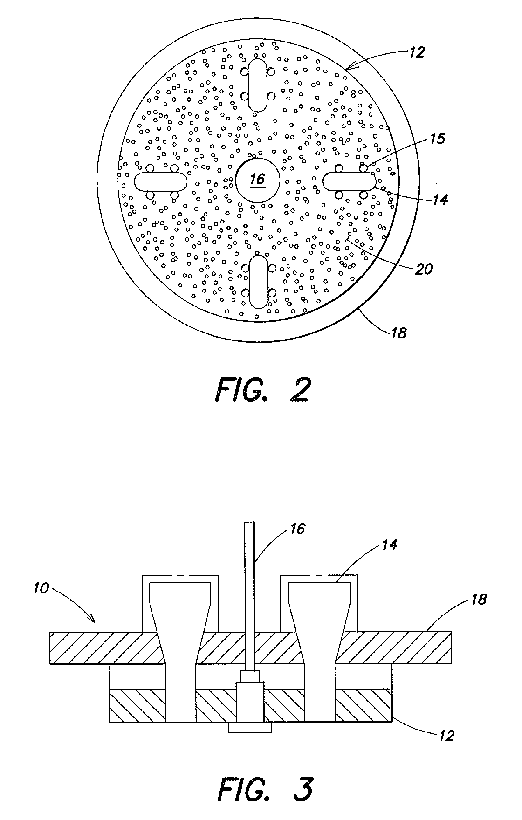
The present invention relates to systems and methods for controlled combustion and decomposition of gaseous pollutants while reducing deposition of unwanted reaction products from within the treatment systems. The systems include a novel thermal reaction chamber design having stacked reticulated ceramic rings through which fluid, e.g., gases, may be directed to form a boundary layer along the interior wall of the thermal reaction chamber, thereby reducing particulate matter buildup thereon. The systems further include the introduction of fluids from the center pilot jet to alter the aerodynamics of the interior of the thermal reaction chamber.
Description
[0001] The present application is a continuation of and claims priority to U.S. patent application Ser. No. 10 / 987,921, filed Nov. 12, 2004, which is hereby incorporated by reference herein in its entirety.BACKGROUND OF THE INVENTION [0002] 1. Field of the Invention [0003] The present invention relates to improved systems and methods for the abatement of industrial effluent fluids, such as effluent gases produced in semiconductor manufacturing processes, while reducing the deposition of reaction products in the treatment systems. [0004] 2. Description of the Related Art [0005] The gaseous effluents from the manufacturing of semiconductor materials, devices, products and memory articles involve a wide variety of chemical compounds used and produced in the process facility. These compounds include inorganic and organic compounds, breakdown products of photo-resist and other reagents, and a wide variety of other gases that must be removed from the waste gas before being vented from the...
Claims
Login to View More Application Information
Patent Timeline
 Patent Type & AuthorityApplications(United States)
IPC IPC(8): F01N3/26
CPCF23D2900/00016F23G7/065F23M2900/05004F23M5/085F23M2900/05002F23J9/00F23G7/06F23M5/08
InventorCHIU, HO-MAN RODNEYCLARK, DANIEL O.CRAWFORD, SHAUN W.JUNG, JAY J.TODD, LEONARD B.VERMEULEN, ROBBERT
OwnerAPPLIED MATERIALS INC