Optical film layer and display device

a display device and optical film technology, applied in the field of display techniques, can solve the problems of reducing affecting the appearance of the display device, and the shading effect of black inks of other colors is not as good as that of black inks, so as to enhance the optical property and the displaying effect of the display device, and reduce the overall thickness of the optical film layer

Pending Publication Date: 2021-12-23
TPK ADVANCED SOLUTIONS
View PDF5 Cites 0 Cited by
  • Summary
  • Abstract
  • Description
  • Claims
  • Application Information

AI Technical Summary

Benefits of technology

[0023]The technical schemes of the present disclosure put the ink layer between the two transparent cover layers, such that light emitted toward an edge of a view area is firstly absorbed and refracted by the lower transparent cover layer and the connection layer and is shaded by the ink layer before entering the upper transparent cover layer. In addition, the ink layer is closer to a light-extracting surface of the optical film layer, such that the ink layer can shade the light emitted toward the edge of the view area more effectively, and an angle at which a user can see the light emitted toward the edge of the view area from a top of the cover layer can be greatly reduced, thereby solving the problem of light leaking from the edge of the view area and enhancing an optical property and a displaying effect of the display device. Furthermore, a softer and thinner film with a UV resistant and anti-glare property may be used as the upper transparent cover layer, such that a level difference between the view area and an edge area caused by the ink layer can be easily overcome, an overall thickness of the optical film layer can be reduced, production costs can be decreased, and units per hour per person can be increased. The problem of light leaking from the edge of the view area is solved without increasing the thickness of the optical film layer, so the ink layer with a desired color can be applied on an edge area according to a product design.

Problems solved by technology

However, shading effects of inks of other colors are not as good as that of a black ink.
When at least two ink layers are printed, the inks are closer to the underlying light source and an angle at which a user can see the light emitted toward the edge of the view area from a top of the cover layer is larger, thus resulting in an edge glow problem.
Therefore, the level difference caused by the ink needs to be overcome during manufacturing, which slows down production.
In order to overcome the level difference caused by the ink, a thicker solid optical clear adhesive is usually adopted, thus resulting in a thickness of the electronic device being increased and cost being increased.

Method used


Image

  • Optical film layer and display device
  • Optical film layer and display device
  • Optical film layer and display device

Examples


Embodiment Construction

[0031]In order to make the objectives, technique schemes, and advantages of the present disclosure become better understood, the disclosure is described in detail below with reference made to the accompanying drawings, embodiments, and examples. It is to be appreciated that the specific embodiments and examples described herein are used to explain the present disclosure only and are not intended to limit the scope of the claims.

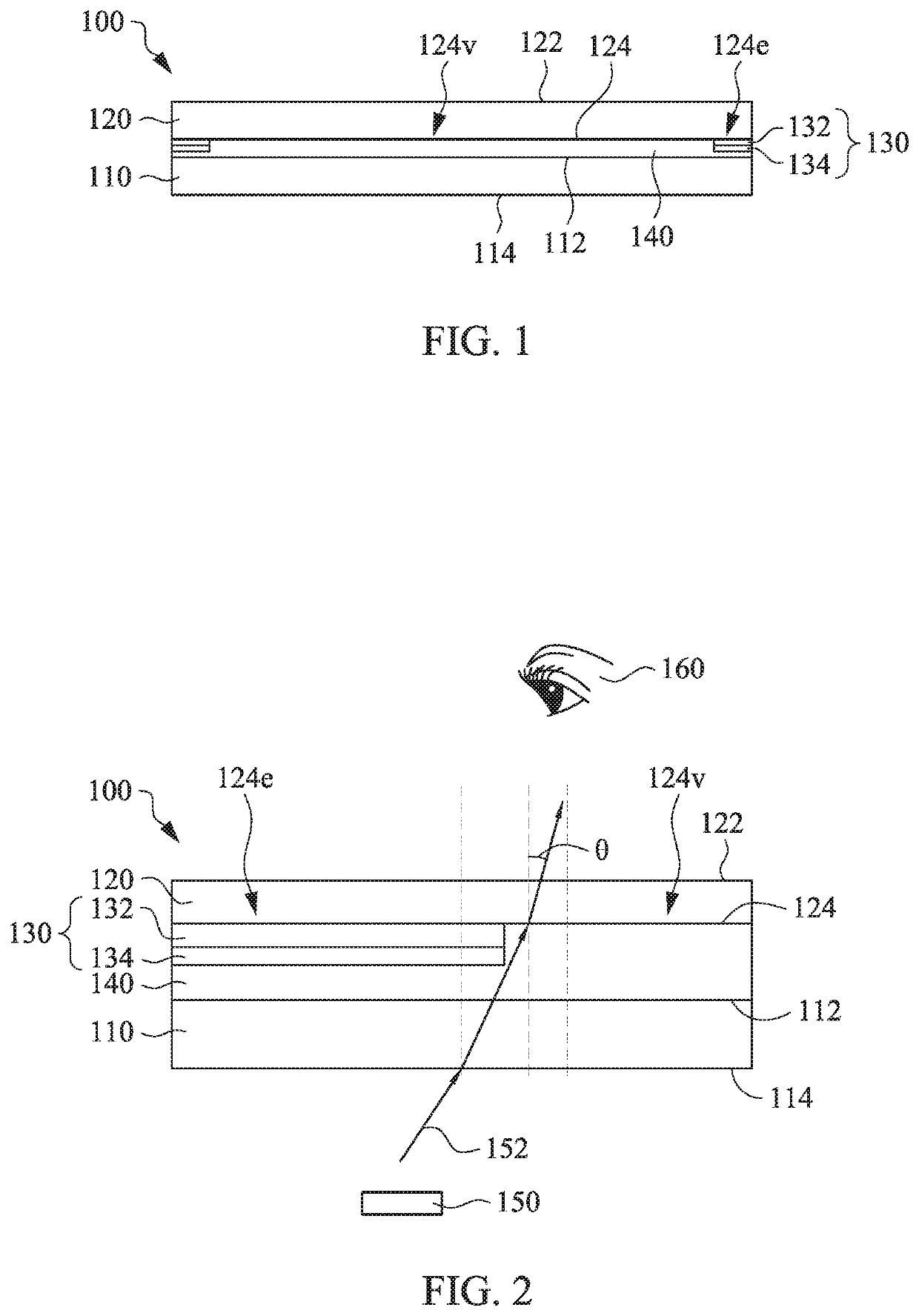
[0032]Referring to FIG. 1, FIG. 1 is a schematic cross-sectional view of an optical film layer 100 in accordance with some embodiments of the present disclosure. The optical film layer 100 includes a first transparent cover layer 110, a second transparent cover layer 120, an ink layer 130, and a connection layer 140. The first transparent cover layer 110 is a plane that is pervious to light and has certain structure ductility. The first transparent cover layer 110 has surfaces 112 and 114, which are opposite to each other. The first transparent cover layer 11...


PUM

PropertyMeasurementUnit
transparentaaaaaaaaaa
opticalaaaaaaaaaa
colorsaaaaaaaaaa

Abstract

The present disclosure provides an optical film layer including a first transparent cover layer, a second transparent cover layer, an ink layer, and a connection layer. The second transparent cover layer is disposed over the first transparent cover layer. The ink layer is disposed on an edge region of a surface of the second transparent cover layer. The connection layer is disposed between the ink layer and the first transparent cover layer and between the surface of the second transparent cover layer and the first transparent cover layer to connect the first transparent cover layer and the second transparent cover layer. By disposing the ink layer between the first transparent cover layer and the second transparent cover layer, a problem of light leaking from an edge of a view area is solved and a display device is thinned, thereby enhancing a display quality of the display device.

Description

RELATED APPLICATIONS[0001]This application claims priority to China Application Serial Number 202010582802.3, filed Jun. 23, 2020, which is herein incorporated by reference.BACKGROUNDField of Disclosure[0002]The present disclosure relates to a display technique, and more particularly, to an optical film layer and a display device.Description of Related Art[0003]Cover layers of display screens of portable electronic products in the current market are typically made from multi-layered plastic composite materials, which increase impact resistance of the cover layer of the screen, enhance product reliability, and reduce cost. An area of a bottom surface of the cover layer of the display screen corresponding to a border area outside of a view area of a display screen is usually printed with an ink layer to hide the underlying devices or structures.[0004]A black ink is beneficial to shade light from an underlying display module. As such, an ink layer printed on an edge area of the cover l...

Claims


Application Information

Patent Timeline
Patent Type & Authority Applications(United States)
IPC IPC(8): G02B1/111G06F1/16
CPCG02B1/111G02B2207/109G06F1/1609G02B1/10G09F9/00G06F3/0412G06F1/1626G06F1/1656G06F2200/1634G02B5/003G02B5/208G02F1/133331
Inventor YAN, JIANBINZHOU, YIDUANLIN, SHUNLONG
Owner TPK ADVANCED SOLUTIONS
Why Eureka
Try Eureka