Reversible dual-position electric connector

a dual-position, electric connector technology, applied in the direction of coupling device connection, two-part coupling device, securing/insulating coupling contact member, etc., can solve the problem of high manufacturing cost of bidirectional electrical connector, low reliability of function, and failure of docking between electrical plug and electrical receptacle, etc. problem, to achieve the effect of reducing manufacturing and assembly costs

Inactive Publication Date: 2022-01-06
TSAI CHOU HSIEN
View PDF57 Cites 1 Cited by
  • Summary
  • Abstract
  • Description
  • Claims
  • Application Information

AI Technical Summary

Benefits of technology

[0006]A main object of the invention is to provide a bidirectional duplex electrical connector, wherein the manufacturing and assembling costs can be decreased, and the duplex docking function can be provided.

Problems solved by technology

However, most users do not have the habit of placing the electrical plug to face the electrical receptacle in the correct direction, and this mistake-proof function causes docking failure between the electrical plug and the electrical receptacle.
In other words, this mistake-proof function brings troubles to the user on the contrary.
However, the conventional bidirectional electrical connector has the high manufacturing cost, and the low reliability of the function.

Method used


Image

  • Reversible dual-position electric connector
  • Reversible dual-position electric connector
  • Reversible dual-position electric connector

Examples


first embodiment

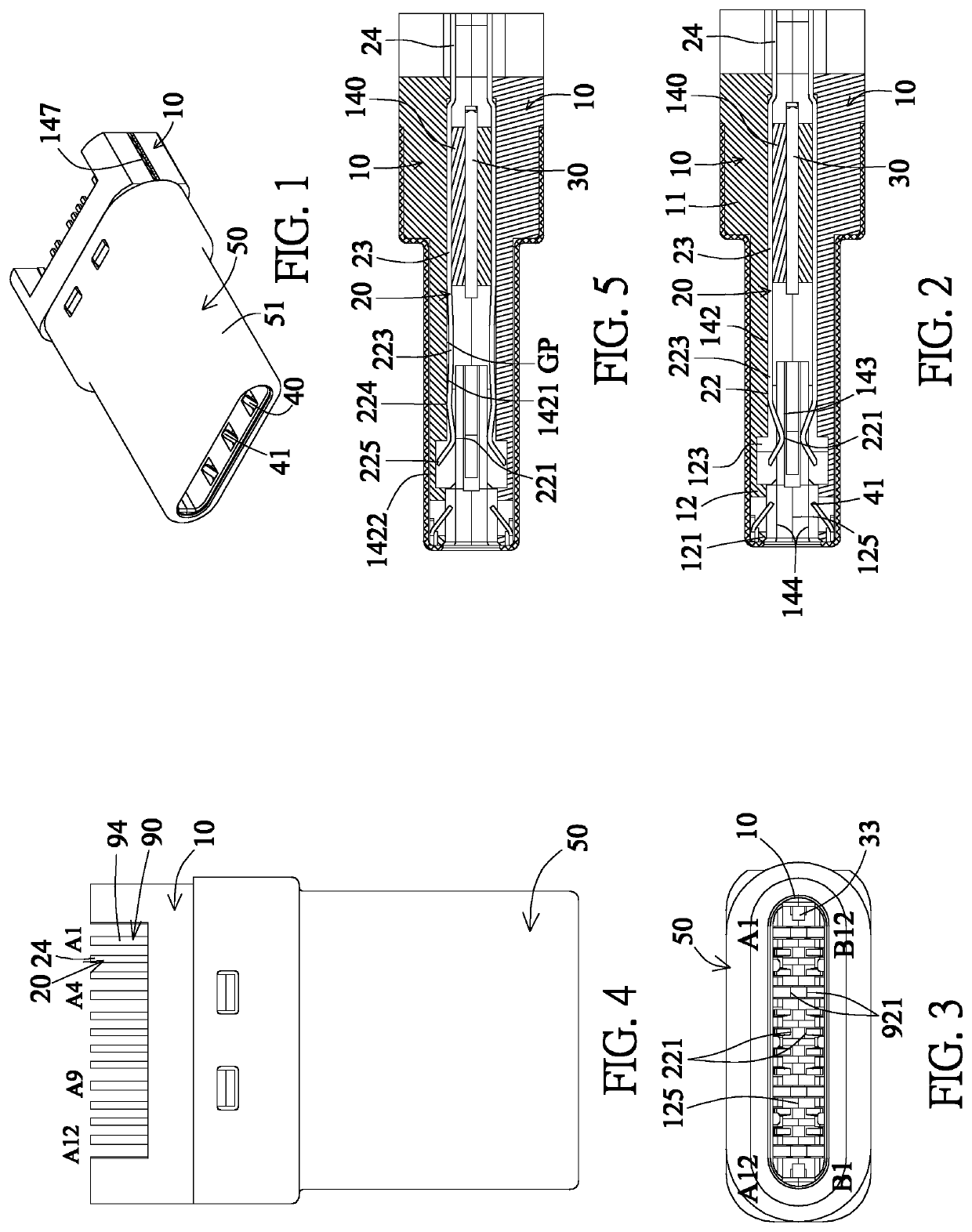
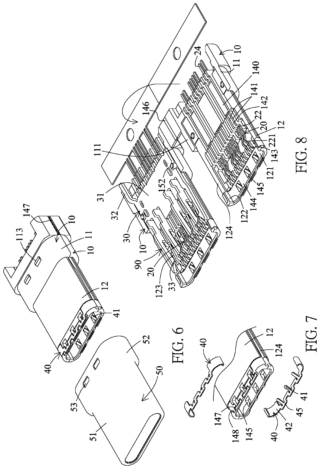
[0104]Referring to FIGS. 1 to 16, a bidirectional duplex USB TYPE-C 3.0 electrical plug according to the invention includes two insulation seats 10, two rows of contacts, a metal partition plate 30, two ground members 40, and a metal housing 50.

[0105]The two insulation seats 10 are stacked in the up-down direction to be an insulator. The insulation seat 10 is integrally provided with a base portion 11 and a docking portion 12. The docking portion 12 is connected to the front end of the base portion 11. The inner surfaces of the base portions 11 of the two insulation seats are provided with connection surfaces 111 resting against each other. One of the insulation seats is provided with an engagement hole 151 engaging with an engagement column 152 of the other insulation seat. The rear section of the base portion 11 is higher than the front section thereof and the outer surface of the rear section is provided with an engagement block 113. The docking portion 12 is provided with a base...

second embodiment

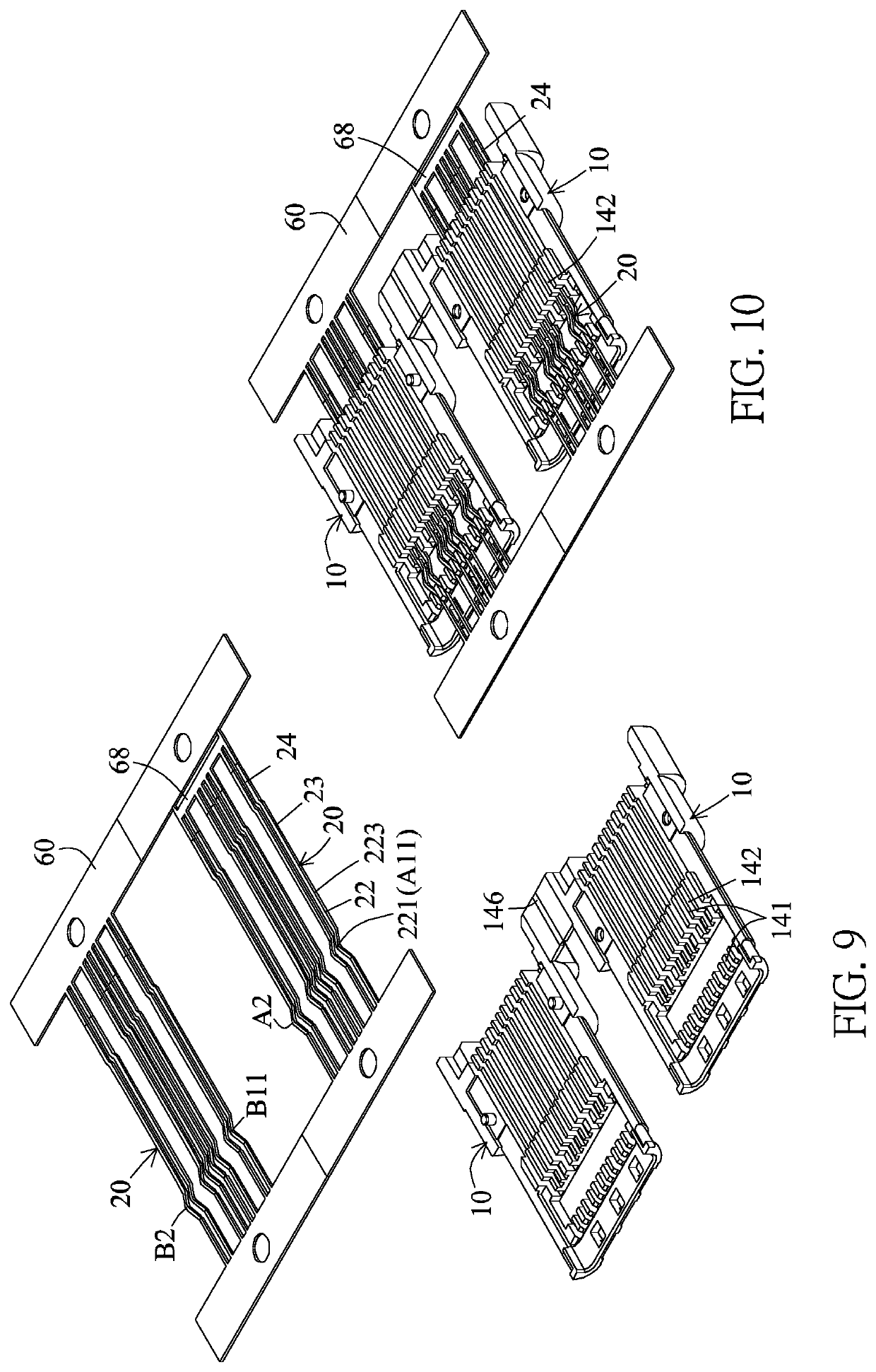
[0154]The manufacturing method of this embodiment is substantially the same as the second embodiment except for the difference that this embodiment has no ground member, and the pins 24 of the upper and lower terminals 20 are in the form of one horizontal row of members flush with each other, wherein the pins 24 of the four pairs of terminals A 1 / B12, A4 / B9, A9 / B4 and A11 / B1 are in an horizontal equal-height and parallel manner or adjacent and close to each other.

[0155]Referring to FIGS. 46 to 49 showing the first modified implementation of the third embodiment of the invention, this embodiment shows a bidirectional duplex USB TYPE-C 2.0 electrical plug, the two insulation seats 10 are stacked in the up-down direction to be an insulator, this embodiment is substantially the same as the third embodiment except for the difference that the base portion 11 of the lower insulation seat 10 of this embodiment extends backwards and projects to form a bonding plate 114 as compared with the b...

fifth embodiment

[0160]Referring to FIGS. 59 and 60 according to the invention, this embodiment provides a flash drive 500 having the electrical connector of the invention. The flash drive 500 includes an outer housing 230, a circuit board 240, an electronic device 250 and an electrical connector 3.

[0161]The circuit board 240 is provided with multiple electroconductive connection points and multiple printed circuits (not shown).

[0162]The electronic device 250 is electrically connected to the circuit board 240. The electronic device 250 includes an electronic unit 251, a control chip 252 and a circuit safety protection device 253. The electronic unit 251 is the main configuration of the electronic device 250, and is a storage unit, which may be a memory, in this embodiment.

[0163]The control chip 252 controls the operation of the electronic unit 251. The circuit safety protection device 253 includes multiple circuit safety protection elements, such as the power safety control chip, anti-over-current e...


PUM


Abstract

A bidirectional duplex electrical connector includes: two insulation seats being each integrally provided with a base portion and a docking portion and being stacked in the up-down direction; a connection slot is formed between the baseplates of the docking portions of the two insulation seats; two rows of terminals assembled into two rows of terminal slots of the two insulation seats in the up-down direction, each of the terminals is integrally provided with, from front to rear, an elastically movable portion and a fixing portion, a front section of the elastically movable portion is provided with a contact projecting from the baseplate to the connection slot; and a metal housing covering the two insulation seats.

Description

CROSS-REFERENCE TO RELATED APPLICATIONS[0001]This application is a continuation of U.S. patent application Ser. No. 16 / 627,507, filed on Mar. 27, 2020 and now issued as U.S. Pat. No. 11,038,310 B2, which claims priority to China Patent Application Ser. No. 201720781911.1, filed on Jun. 30, 2017, the content of which is incorporated herein by reference. This U.S. patent application Ser. No. 16 / 627,507 is a CIP (continuation-in-part) of pending U.S. patent application Ser. No. 16 / 071,613, filed on Jul. 20, 2018, and pending U.S. patent application Ser. No. 16 / 166,433, filed on Oct. 22, 2018, the contents of which are incorporated herein by reference.BACKGROUND OF THE INVENTIONField of the Invention[0002]The invention relates to an electrical connector, and more particularly to a bidirectional duplex electrical connector.Description of the Related Art[0003]At present, because the functions of various electronic products are becoming more and more powerful and handheld devices are also ...

Claims


Application Information

Patent Timeline
Patent Type & Authority Applications(United States)
IPC IPC(8): H01R24/60H01R13/6581H01R13/502
CPCH01R24/60H01R2107/00H01R13/502H01R13/6581H01R13/501H01R13/41H01R13/6583H01R13/6658H01R43/24H01R31/065
Inventor TSAI, CHOU HSIEN
Owner TSAI CHOU HSIEN
Why Eureka
Try Eureka