Wearable robotic device for moving a user

a robotic device and user technology, applied in the field of wearable robotic devices, can solve the problems of high cost of speed and metabolic consumption, large volume of mechanical and electronic components, and general complexity of active prostheses

Pending Publication Date: 2022-01-13
SCUOLA SUPERIORE DI STUDI UNIVERSITARI E DI PERFEZIONAMENTO SANTANNA
View PDF3 Cites 0 Cited by
  • Summary
  • Abstract
  • Description
  • Claims
  • Application Information

AI Technical Summary

Benefits of technology

[0011]It is therefore a feature of the present invention to provide a robotic device for the movement of a user that has the practicality of using a prosthesis or a passive exoskeleton, who however does not need energy compensation by the user to obtain sufficient thrust to perform a step.

Problems solved by technology

The amputee will have to compensate with the residual limbs for the absence of energy supply, at the expense of speed and metabolic consumption.
However, active prostheses have several disadvantages, since mechanical and electronic components are generally very complex and heavy.
This entails higher costs and less reliability than passive prostheses.
In addition, in the event of a malfunction or a lack of electricity, these prostheses lose all their functionality becoming rigid and heavy appendages that can also totally block the user's mobility.
However, in this device the release of mechanical energy takes place simply at the end of the accumulation phase and is in no way related to the patient's step phase.
This means that the impulse provided by the elastic element is not synchronized with the user's pace, significantly reducing the quality of motor assistance provided by the device.

Method used


Image

  • Wearable robotic device for moving a user
  • Wearable robotic device for moving a user
  • Wearable robotic device for moving a user

Examples


Embodiment Construction

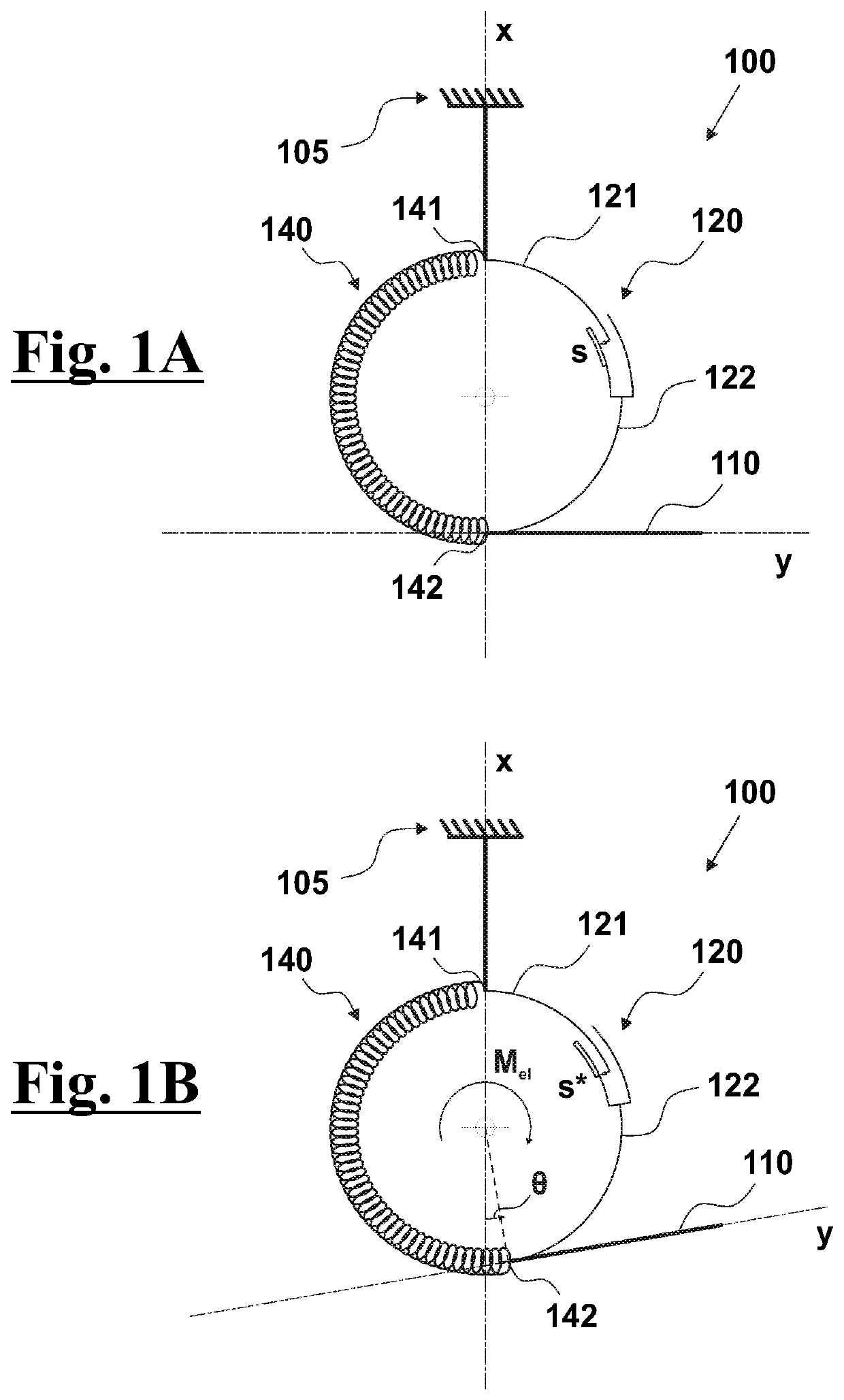
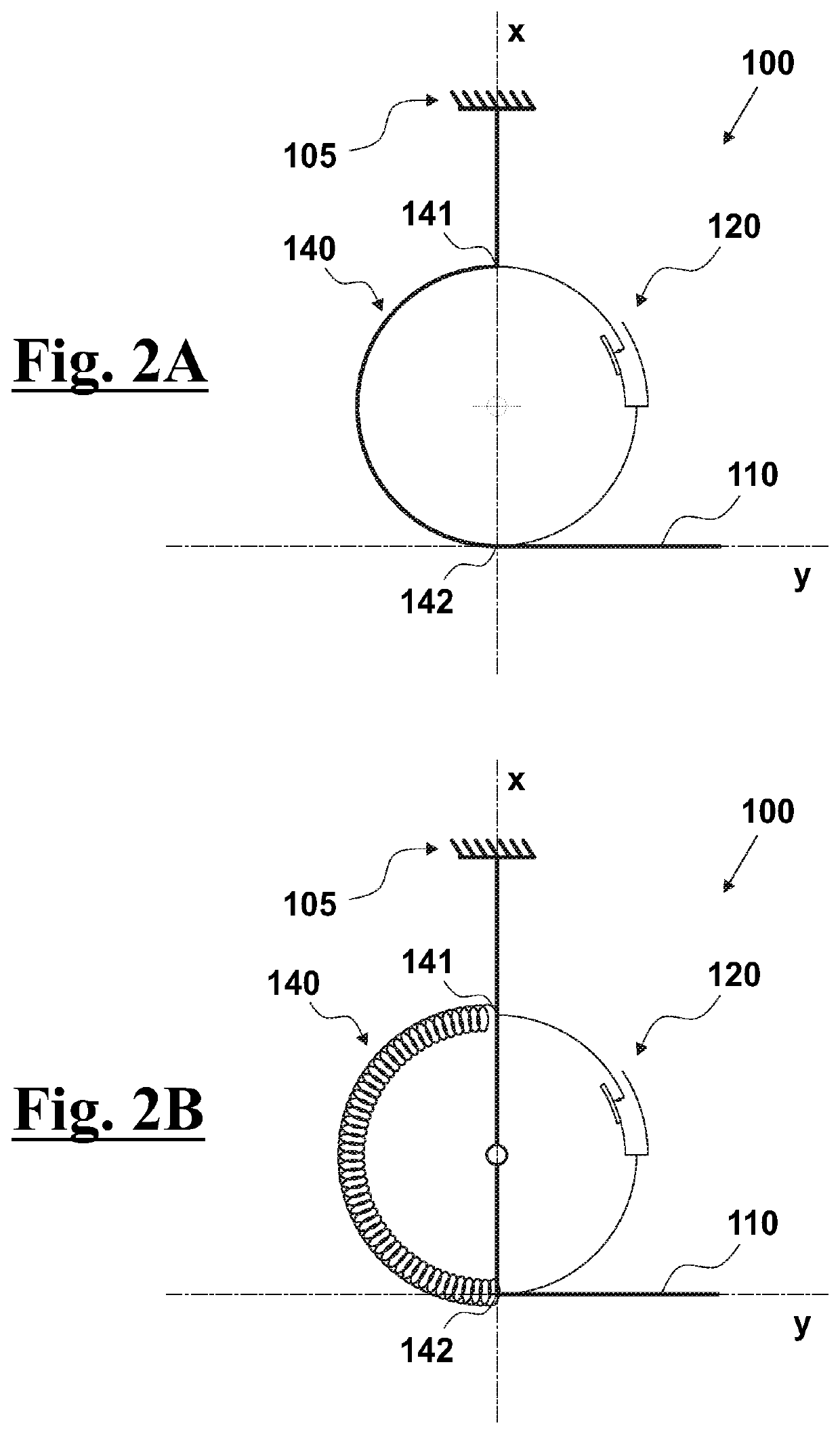
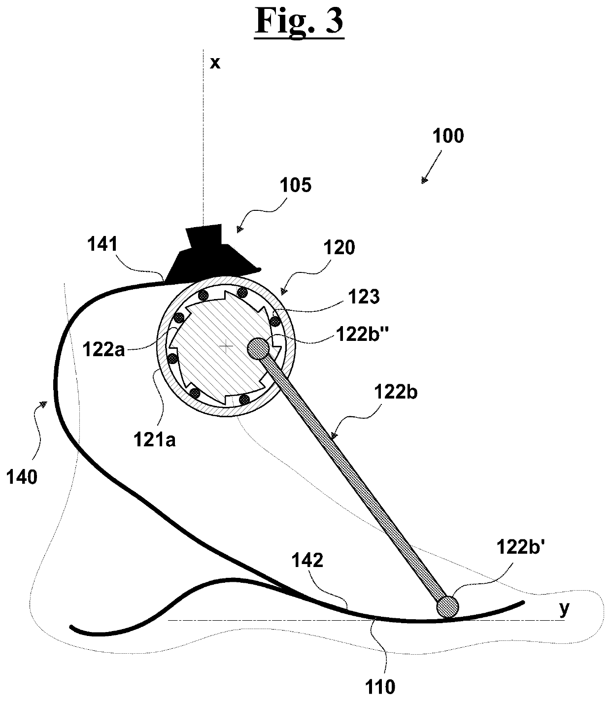
[0030]With reference to FIGS. 1A and 1B, the robotic device 100, according to the present invention, comprises an interface frame 105, arranged to connect the robotic device 100 to a lower limb or to a lower limb prosthesis, a lower portion 110 and a resilient element 140 having a first end 141 connected to the interface frame 105 and a second end 142 connected to the lower portion 110.

[0031]Considering an axis x integral to the interface frame 105 and an axis y integral to the lower portion 110, the resilient element 140 can be deformed as a function of an angular variation θ between the axis x and the axis y, as shown in FIG. 1B.

[0032]The robotic device 100 also comprises a switching device 120 comprising a first element 121, connected to the interface frame 105, and a second element 122, connected to the lower portion 110. In particular, the first and the second element 121,122 are adapted to carry out a relative movement s as a function of the angular variation θ between the axi...


PUM


Abstract

A robotic device (100) for the movement of a user, said robotic device (100) comprising an interface frame (105) arranged to connect the robotic device (100) to a lower limbs or to a prosthesis of lower limbs, said interface frame (105) being integral to an axis x, a lower portion (110) integral to an axis y, a resilient element (140) having a first end (141) connected to the interface frame (105) and a second end (142) connected to the lower portion (110), said resilient element (140) being arranged to deform as a function of an angular variation θ between the axis x and the axis y, a switching device (120) comprising a first element (121), connected to the interface frame (105), and a second element (122), connected to the lower portion (110), said first and second element (121,122) arranged to carry out a relative movement s as a function of the angular variation θ between the axis x and the axis y. In particular, the robotic device (100) is configured in such a way that when the relative movement s is less than a predetermined threshold value s* and the angular variation θ increases, the robotic device (100) is in a first configuration and the resilient element (140) deforms storing elastic energy, said switching device (120) being configured in such a way that in the first configuration the relative movement s can take place only in one direction of motion, and that when the relative movements is equal to the predetermined threshold value s*, the robotic device (100) passes in a second configuration and the resilient element (140) releases elastic energy creating an angular moment Mel arranged to oppose the increasing of the angular variation θ.

Description

FIELD OF THE INVENTION[0001]The present invention relates to the field of robotic devices for assisting the movement of a user.[0002]In particular, the invention relates to a robotic device for the improvement of a prosthesis or an exoskeleton of a lower limb.DESCRIPTION OF THE PRIOR ART[0003]As known, different foot, ankle or knee prostheses may be prescribed to provide adequate limb amputees.[0004]For a basic functionality, that is to get up and be able to walk, a SACH (Solid Ankle Cushioned Heel) foot is adopted. It is a stiff foot that offers only support and no energy contribution to walking. The amputee will have to compensate with the residual limbs for the absence of energy supply, at the expense of speed and metabolic consumption.[0005]An increase in mobility can be obtained by using an ESAR (Energy Storage And Return) foot, comprising an elastic carbon structure capable of storing mechanical energy during the first part of the support phase (weight acceptance) of the walk ...

Claims


Application Information

Patent Timeline
Patent Type & Authority Applications(United States)
IPC IPC(8): A61F2/66A61F2/70B25J9/00B25J9/10
CPCA61F2/66A61F2/70A61F2002/704B25J9/1005A61F2002/6657B25J9/0006
Inventor BALDONI, ANDREAFANTOZZI, MATTEOCREA, SIMONAVITIELLO, NICOLA
Owner SCUOLA SUPERIORE DI STUDI UNIVERSITARI E DI PERFEZIONAMENTO SANTANNA
Why Eureka
Try Eureka