Image forming apparatus

a technology of image forming apparatus and forming drum, which is applied in the direction of electrographic process apparatus, instruments, optics, etc., can solve the problems of color misregistration, inability to reduce the influence of speed fluctuation of driving gear, and inability to address the misregistration among the respective colors caused by the rotational fluctuation of the plurality of photosensitive drums. to achieve the effect of reducing misregistration

Active Publication Date: 2022-01-13
CANON KK
View PDF0 Cites 0 Cited by
  • Summary
  • Abstract
  • Description
  • Claims
  • Application Information

AI Technical Summary

Benefits of technology

[0008]The present disclosure is directed to reducing misregistration among respective colors due to rotational fluctuations among a plurality of photosensitive drums, without performing rotational phase control for aligning the rotational phases with one another.

Problems solved by technology

The tandem-type image forming apparatus thus has an issue where the occurrence of speed fluctuations of the plurality of photosensitive drums and the intermediate transfer belt causes color misregistration in which the superimposed images are misaligned and the respective colors are misregistered.
However, this technique fails to reduce the influence of speed fluctuations of driving gears that drive the photosensitive drums.
However, the technique discussed in Japanese Patent No. 5130507 has an issue where the composite amplitudes are matched by connecting the driving gears and the couplings while relatively shifting them, but the rotational phases are not aligned with one another, thereby not addressing misregistration among the respective colors, which is caused by rotational fluctuations among the plurality of photosensitive drums.
More specifically, the technique discussed in Japanese Patent No. 5130507 has an issue where the misregistration among the respective colors caused by the rotational fluctuations among the plurality of photosensitive drums is not addressed unless the driving gears and the couplings with the composite amplitudes matched are further subjected to rotational phase control for aligning the rotational phases with one another.

Method used


Image

  • Image forming apparatus
  • Image forming apparatus
  • Image forming apparatus

Examples


Embodiment Construction

[0018]Hereinafter, exemplary embodiments of the present disclosure will be described in detail with reference to the drawings. Dimensions, materials, shapes, and relative arrangement of components according to the exemplary embodiments described below may be changed as appropriate based on the configuration of an apparatus to which any of the exemplary embodiments of the present disclosure is applied and various kinds of conditions, and are not intended to limit the scope of the present disclosure only thereto.

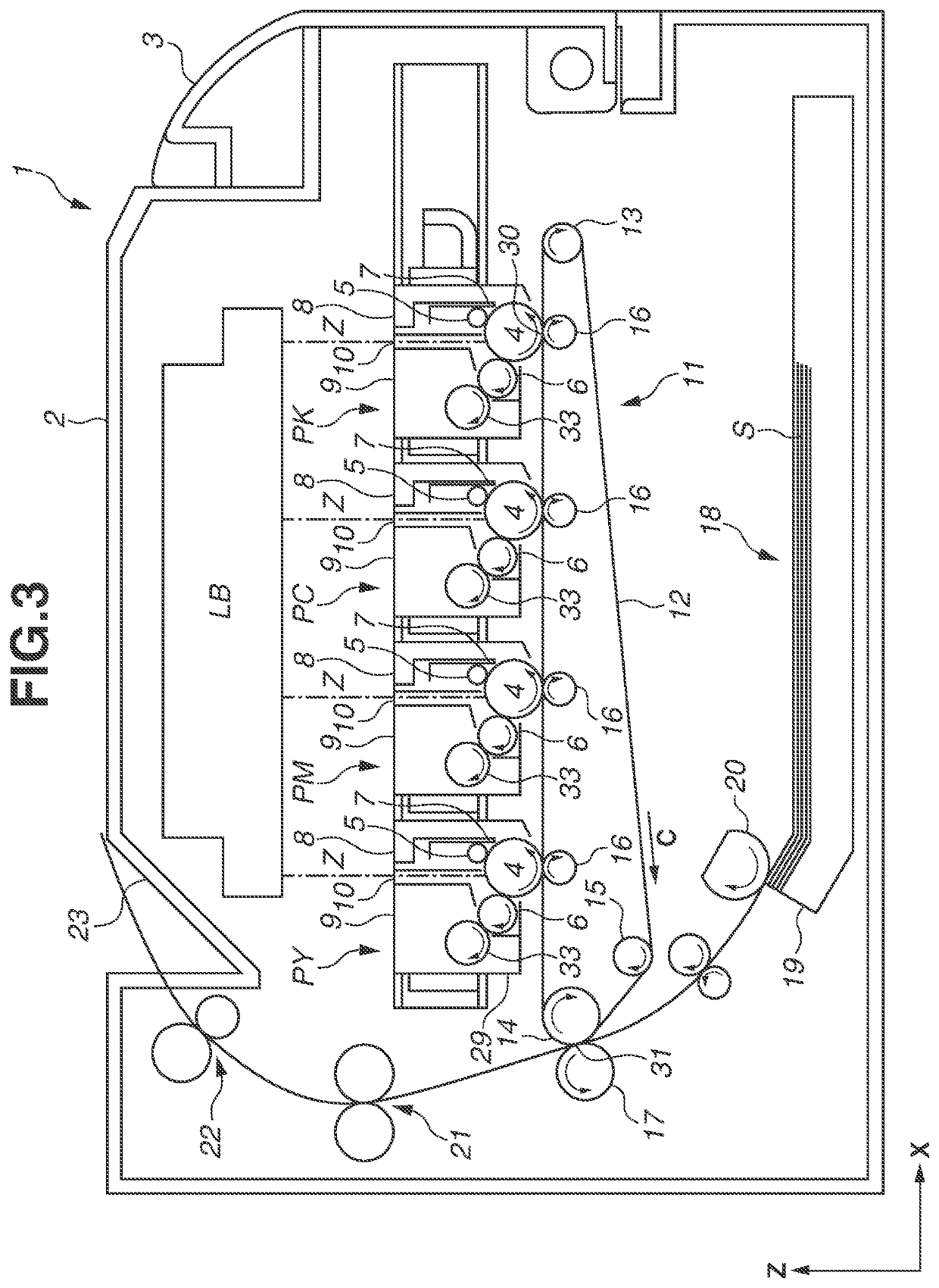
[0019]Hereinafter, an image forming apparatus including a driving unit according to a first exemplary embodiment will be described. In the following exemplary embodiments, a full-color image forming apparatus to which four process cartridges are detachably attached will be described as an example of an image forming apparatus. The number of process cartridges attached to an image forming apparatus is not limited to four, and may be appropriately set as necessary.

[0020]First, a...


PUM


Abstract

An image forming apparatus includes a driving unit having a first drum gear, a first coupling member, a second drum gear, and a second coupling member. The first coupling member is provided at a first position of the first drum gear. The second coupling member is provided at a second position of the second drum gear and is configured to rotate together with the second drum gear. A first angle from a first meshing position to a first transfer position in a first direction and a second angle from a second meshing position to a second transfer position in a second direction are different from each other. The second position of the second drum gear is shifted from a position corresponding to the first position of the first drum gear by a difference between the first angle and the second angle in a direction opposite of the second direction.

Description

BACKGROUNDField[0001]The present disclosure relates to an image forming apparatus including a driving unit that drives a plurality of photosensitive drums.Description of the Related Art[0002]As an electrophotographic color image forming apparatus, there is known a tandem-type image forming apparatus including independent image forming units for respective colors. The tandem-type image forming apparatus transfers images from the respective photosensitive drums of the image forming units onto an intermediate transfer belt so as to superimpose the images, and further transfers the images from the intermediate transfer belt onto a recording medium all at once. The tandem-type image forming apparatus thus has an issue where the occurrence of speed fluctuations of the plurality of photosensitive drums and the intermediate transfer belt causes color misregistration in which the superimposed images are misaligned and the respective colors are misregistered.[0003]To reduce the color misregis...

Claims


Application Information

Patent Timeline
Patent Type & Authority Applications(United States)
IPC IPC(8): G03G15/00
CPCG03G15/757G03G15/0189
Inventor YAMAGUCHI, NORITOMOFUKASE, YASUHIROKAWANAMI, TAKEO
Owner CANON KK
Why Eureka
Try Eureka