Light scanning apparatus and image forming apparatus

a scanning apparatus and light beam technology, applied in the direction of inking apparatus, instruments, electrographic processes, etc., can solve the problems of limited manufacturing accuracy, degrade image quality, and not a complete regular polygon, and achieve the effect of suppressing fluctuations in scanning magnification of light beams

Inactive Publication Date: 2013-06-18
CANON KK
View PDF10 Cites 0 Cited by
  • Summary
  • Abstract
  • Description
  • Claims
  • Application Information

AI Technical Summary

Benefits of technology

[0027]The present invention has been made in view of the above-mentioned problems, and it is therefore an object thereof to suppress fluctuations in scanning magnification of a light beam.
[0030]According to the present invention, the fluctuations in scanning magnification of the light beam can be suppressed so as to form a high quality image in which image misregistration is reduced.

Problems solved by technology

The rotary polygon mirror 3 is not a complete regular polygon because of limited manufacturing accuracy.
Actually, however, the scanning speed of the laser beam on the photosensitive drum fluctuates a little every scanning, and the formed electrostatic latent image therefore suffers from magnification fluctuations in the laser beam scanning direction, which thus degrades image quality.
Further, another factor causing the fluctuations in scanning speed of the laser beam is the accuracy of the surface shape of the rotary polygon mirror.
The rotary polygon mirror is desired to be an ideal regular polygon, but actually has a manufacturing error.
When the mirror surface shows a convex tendency, the scanning speed of the laser beam is slower than that measured when the mirror surface is an ideal flat surface, thus resulting in a small scanning magnification.
When the mirror surface shows a concave tendency, the scanning speed of the laser beam is faster, thus resulting in a large scanning magnification.
The above-mentioned related art, however, has the following problems.
In other words, specifically, the rotary speed of the rotary polygon mirror fluctuates with the acceleration or deceleration, with the result that fluctuations in magnification in an electrostatic latent image occur.
H10-148773 can eliminate long-period fluctuations in rotary speed of the rotary polygon mirror, but cannot eliminate the above-mentioned short-period fluctuations occurring in association with acceleration or deceleration of the rotary polygon mirror.
However, the fluctuations in scanning speed in association with acceleration or deceleration of the rotary polygon mirror are short-period fluctuations such that the scanning speed varies every scanning made by the rotary polygon mirror.
H10-148773, the rotary speed is detected every revolution of the rotary polygon mirror to correct the write timing, which cannot eliminate the above-mentioned short-period fluctuations, thus resulting in a control error.
In reality, the magnification fluctuations among the mirror surfaces show a difference between when the rotary polygon mirror is accelerated and decelerated, thus also resulting in a control error.

Method used


Image

  • Light scanning apparatus and image forming apparatus
  • Light scanning apparatus and image forming apparatus
  • Light scanning apparatus and image forming apparatus

Examples


first embodiment

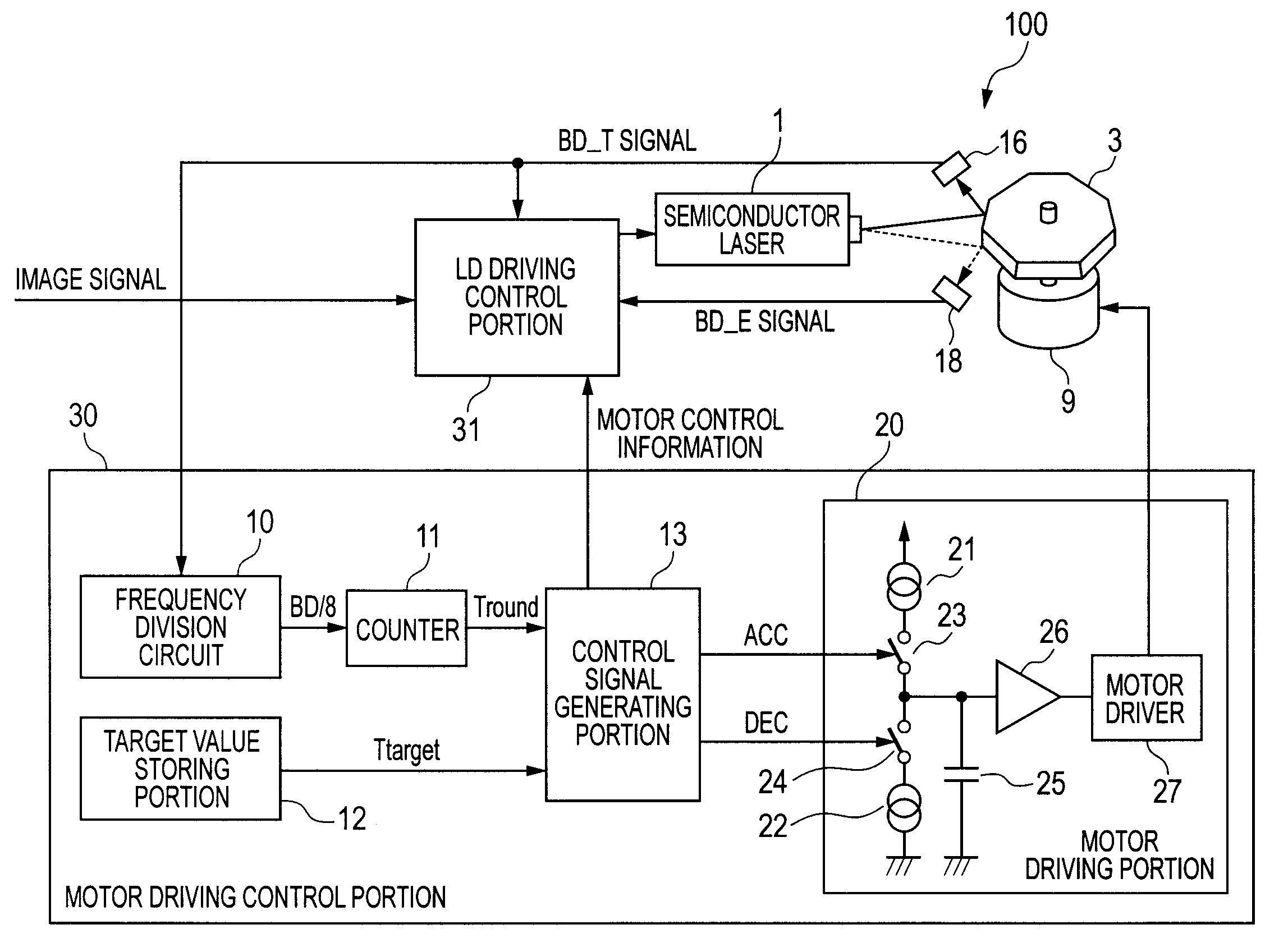
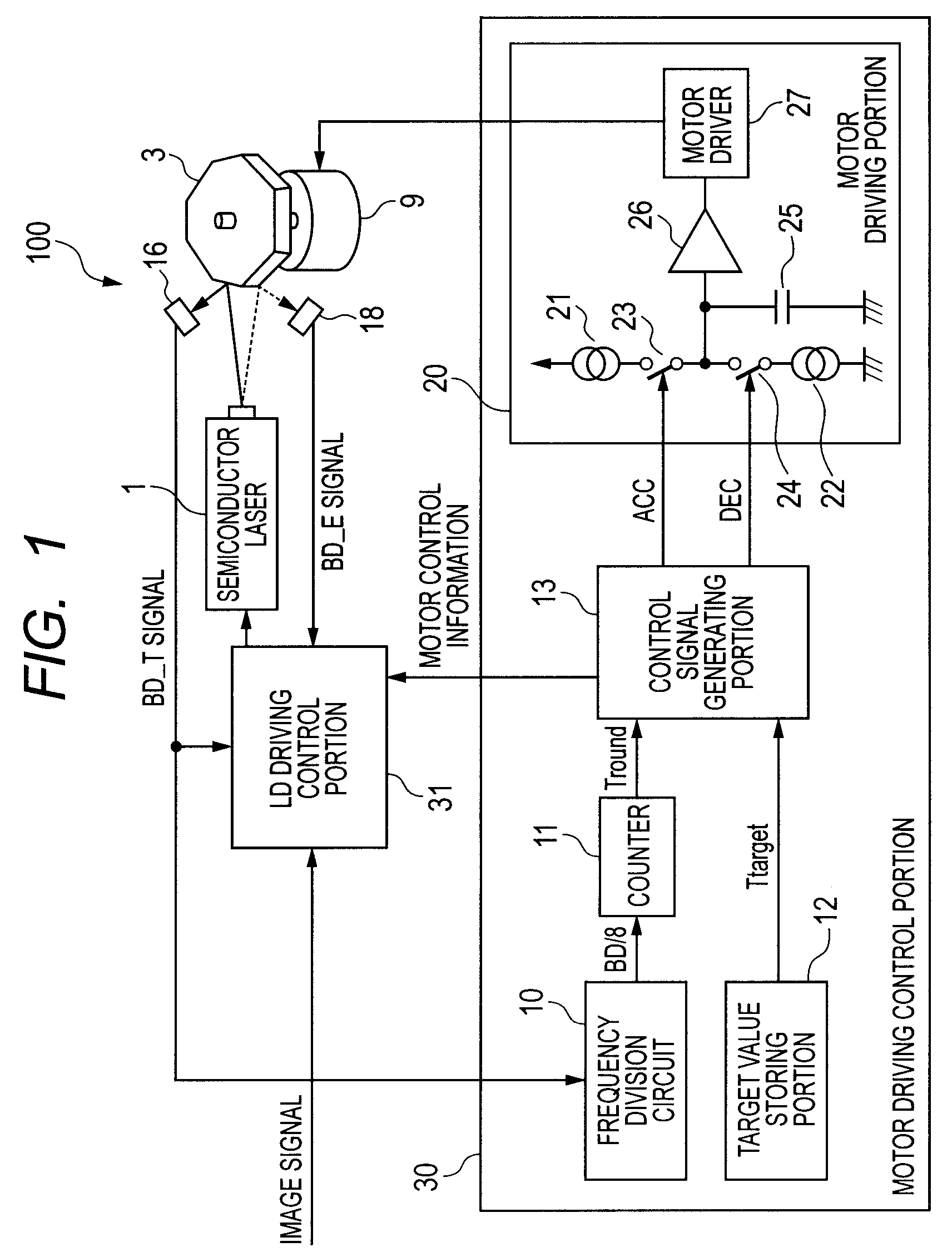
[0049]FIG. 1 is a diagram illustrating a light scanning apparatus 100 according to a first embodiment of the present invention. The light scanning apparatus 100 is provided in an image forming apparatus including an image forming portion that forms an image on a recording medium by an electrophotographic process.

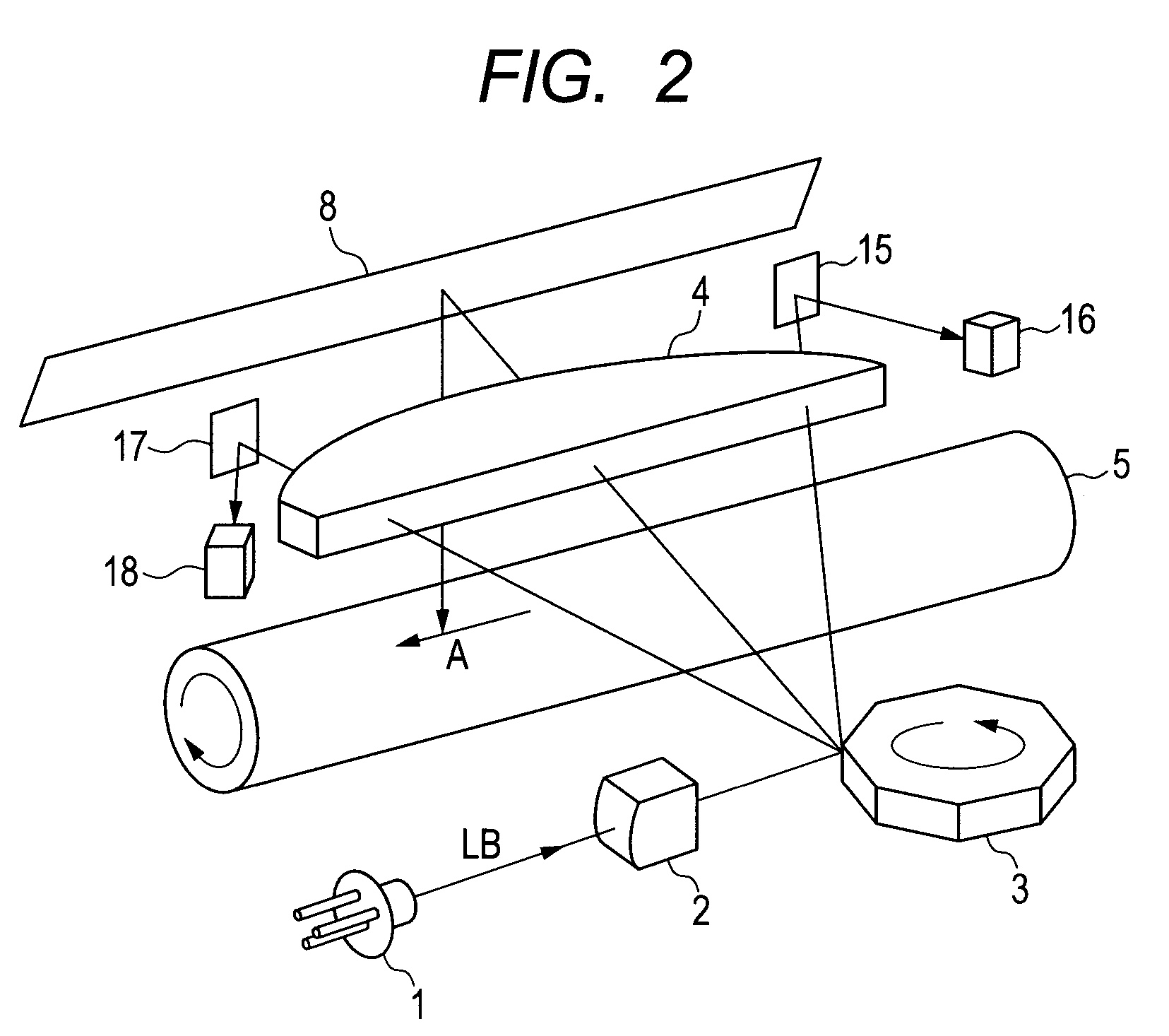
[0050]FIG. 2 illustrates a schematic structure of a light scanning system according to the first embodiment.

[0051]Note that, in FIG. 2, parts which are functionally equivalent to those in the related art illustrated in FIG. 14 are denoted by the same reference symbols and description thereof is thus omitted.

[0052]Referring to FIG. 2, a first BD reflecting mirror 15 and a first BD sensor 16 are disposed outside an image region on a scanning start side. Further, a second BD reflecting mirror 17 and a second BD sensor 18 are disposed outside the image region on a scanning end side. By measuring a time interval between detection by the first BD sensor and detection by the second...

second embodiment

[0093]FIG. 8 is a control block diagram according to a second embodiment of the present invention, schematically adding the driving motor 9 and the like. Note that, the structure of the laser beam scanning system is the same as that in the related art illustrated in FIG. 14 and description thereof is thus omitted. Further, parts which are similar to those in the first embodiment such as the motor driving control portion 30 are not described repeatedly.

[0094]A reference mark detecting portion 72 detects a reference mark 80 (FIG. 9) of the rotary polygon mirror 3 for discriminating the mirror surface. FIG. 9 is a top view of the rotary polygon mirror 3. FIG. 10 is a side view of the rotary polygon mirror 3.

[0095]Referring to FIG. 9, on the top surface of the rotary polygon mirror 3, the reference mark 80 in which only a part of the circumference of the reflectance is different from other part of the circumference is formed. With the rotary polygon mirror 3 being rotated, an optical se...


PUM


Abstract

A light scanning apparatus including: a light source to emit a laser beam; a light source driving unit to turn on and off the light source according to image data and a pixel clock; a rotary polygon mirror to deflect the light beam; a motor to rotationally drive the rotary polygon mirror; and a control unit to control a rotary speed of the motor to generate an acceleration control signal for accelerating the rotary speed and a deceleration control signal for decelerating the rotary speed, wherein for the acceleration control signal, the driving unit corrects the frequency of the pixel clock to be higher than the frequency, which is before the acceleration control, and for the deceleration control signal, the driving unit corrects the frequency of the pixel clock to be lower than the frequency, which is before the deceleration control.

Description

BACKGROUND OF THE INVENTION[0001]1. Field of the Invention[0002]The present invention relates to a light scanning apparatus for deflecting a laser beam so that the laser beam scans a photosensitive member, and an image forming apparatus having the light scanning apparatus.[0003]2. Description of the Related Art[0004]In recent years, digital copying machines and digital printers have rapidly become widespread, and various types of image forming apparatus have been put into practical use.[0005]A so-called laser beam printer, which is one image forming apparatus using an electrophotographic process, modulates a laser beam output from a semiconductor laser according to an image signal and deflects the laser beam by a rotary polygon mirror. The laser beam deflected by the rotary polygon mirror scans a photosensitive member of a photosensitive drum or the like. When the laser beam scans the photosensitive drum, an electrostatic latent image is formed on the photosensitive drum. The latent...

Claims


Application Information

Patent Timeline
Patent Type & Authority Patents(United States)
IPC IPC(8): B41J2/44G02B26/10
CPCG06K15/1219G02B26/127
Inventor KIYAMA, KOTA
Owner CANON KK
Why Eureka
Try Eureka