Magnetic Lock and Release Clasp System

Active Publication Date: 2022-01-27
BACA ANGELA YVONNE
View PDF0 Cites 0 Cited by
  • Summary
  • Abstract
  • Description
  • Claims
  • Application Information

AI Technical Summary

Benefits of technology

[0008]This invention utilizes a magnetized clasp with a built in lock and release system that would allow you to secure two connecting ends of a chain or rope to make a circular connection, with the guided assistance of a magnetic field. The magnetic field also serves as an extra means to further ensure a strong connection when the clasp is closed to ensure the connection isn't compromised and jewelry is lost. The lock and release feature of the clasp allow for the clasp portion to remain open while attempting to connect two rings. The imbedded magnet helps guide the user to easily locate the opening of the clasp. For example, these two pieces can be connected to eit

Problems solved by technology

With current connections related to jewelry, there is great difficulty adjoining two pieces of small metal circles to make a secure linkage due to dexterity issues as well as visual limitations due to the small size of adjoining ends and their openings.
This can become further complicated when working under difficult circumstances such as when you cannot visibly obser

Method used


Image

  • Magnetic Lock and Release Clasp System
  • Magnetic Lock and Release Clasp System
  • Magnetic Lock and Release Clasp System

Examples


Example

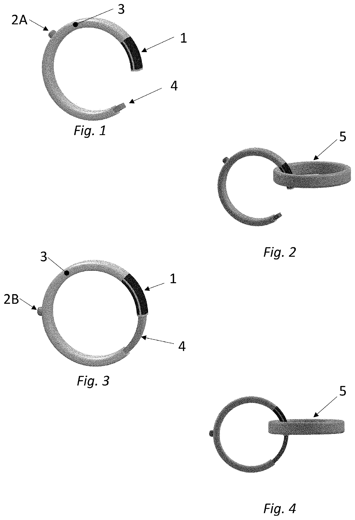
[0016]Illustrated embodiments of this invention can be used to open a section of a circular clasp and allow it to remain / lock in the open position. Pushing on the button or knob allows the retracted circle or plunger to close, making a secure connection. The magnetic section on the clasp guides the ferromagnetic opposing ring to the opening to connect the two rings. The magnetic section also makes a more secure closure when the clasp is closed. Both of these invention embodiments improve upon limitations in the previous Spring Ring Patent No 267,112 which only focused on the coil spring and plunger in association with opening and closing the clasp.

[0017]The illustrated embodiments of the invention use components to lock the clasp in the open position as well as guide the opposing ring to mate with the clasp. FIG. 1 diagram illustrates the exemplary embodiments of the Magnetic Lock and Release Clasp in isolation and in the open position. FIG. 1 will be used to identify and refer to t...


PUM


Abstract

The invention has two primary claims which in manipulating a clasp and connection to an opposing ring. Although applicable to any clasp system, it is especially relevant to jewelry connections in necklaces or bracelets whereby the connecting rings are quite small requiring visual acuity and manual dexterity to operate. This invention builds upon prior art described in the Spring Ring Patent No 267,112, Nov. 7, 1882. The first claim of this invention allows the user to pull back the plunger within the clasp ring and set it in a locked and open position allowing the user to gain manual dexterity for guiding the clasp towards the opposing ring. The second claim adds a feature in which a magnetic portion of the clasp and opposing ring allows the two rings to be guided towards each other and position them for connection. Since visual acuity is necessary, this magnetic guide is critical.

Description

CROSS REFERENCE TO RELATED APPLICATIONS[0001]This patent is related to Spring Ring Patent No 267,112, Nov. 7, 1882STATEMENT REGARDING FEDERALLY SPONSORED RESEARCH OR DEVELOPMENT[0002](Not Applicable)REFERENCE TO SEQUENCE LISTING, A TABLE, OR A COMPUTER PROGRAM LISTING COMPACT DISK APPENDIX[0003](Not Applicable)BACKGROUND OF THE INVENTION[0004]This invention pertains to a clasp design that can be used for jewelry or chain closures, primarily related to a necklace or bracelet but also applicable to a chain or bike lock type system. The clasp generally has an attachment loop so that it can be attached to necklaces, chains, etc. with a spring loaded plunger within a bore of a curved body such as a circle or oval.[0005]Related Patent Classifications: CPC Definition A44B Buttons, pins, buckles, slide fasteners, or the like (fastenings)US Class 24 series; Class 413 Joints and Connections; Class D11 Jewelry, Symbolic Insignia, and Ornaments[0006]The prior art related to this invention is as...

Claims


Application Information

Patent Timeline
IPC IPC(8): A44C5/20
CPCA44C5/2009A44D2203/00A44C5/2014
Inventor BACA, ANGELA YVONNE
Owner BACA ANGELA YVONNE
Why Eureka
Try Eureka