
Workpiece carrier for production lines, or pallet, with adjustable supports

Active Publication Date: 2005-07-19
ATOP SPA
View PDF4 Cites 3 Cited by
  • Summary
  • Abstract
  • Description
  • Claims
  • Application Information

AI Technical Summary

Benefits of technology

[0014]It is an object of the present invention to provide a pallet for automatic production lines having support elements with variable distance that can be easily located in predetermined points, and that share the weight on two bearing elements.
[0015]It is another object of the present invention to provide a pallet that can adapt without any change to work both on a line with automatic adjustment station and on a line with manual adjustment of the support distance.
[0016]It is a further object of the present invention to provide a pallet whose parts are easily and independently replaceable.
[0021]Advantageously, the bridges ends have opposed inclination as well as the surfaces of the bars have opposed inclination, whereby the matching of a bridge and two bars is substantially self-centring and allows a quick adjustment of the position of the bridges on the pallet.
[0023]Each bridge is provided with at least a magnet at one end that allows a solid fastening of it at the base of the pallet. Therefore, the presence of the magnet and of the positive engagement between the bars and the bridges ends assure a high steadiness of support of the workpiece that cannot move in a desired direction, allowing a precise grip by manipulating means located along the production line.

Problems solved by technology

Production lines that are not flexible exist, i.e, prepared to operate on workpieces having all the same size or workpiece families of substantially alike size.
In all the various embodiments presented, however, the pallet is structurally complex and heavy to make, and requires complex means for adjusting.

Method used


Image

  • Workpiece carrier for production lines, or pallet, with adjustable supports
  • Workpiece carrier for production lines, or pallet, with adjustable supports
  • Workpiece carrier for production lines, or pallet, with adjustable supports

Examples


Embodiment Construction

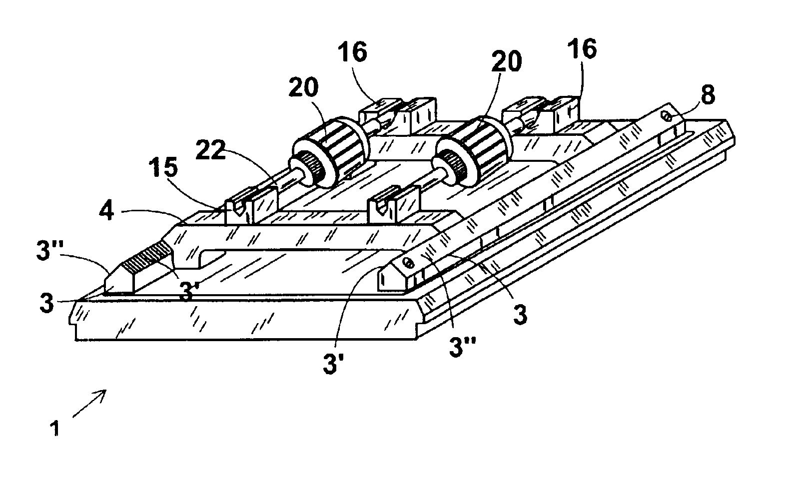
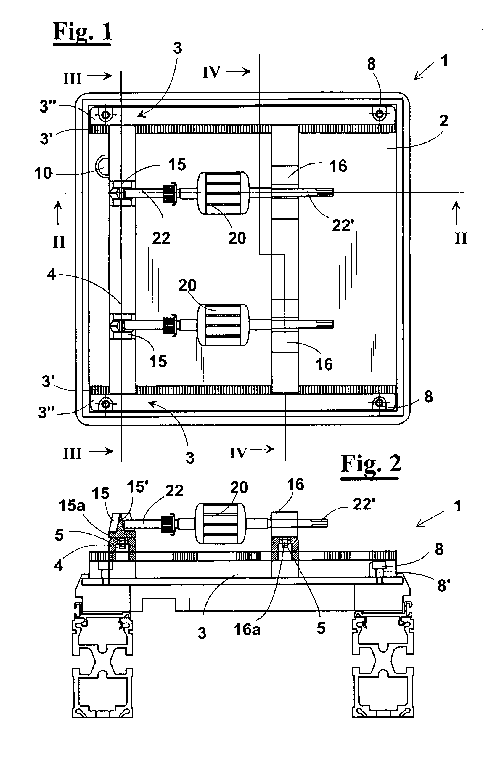
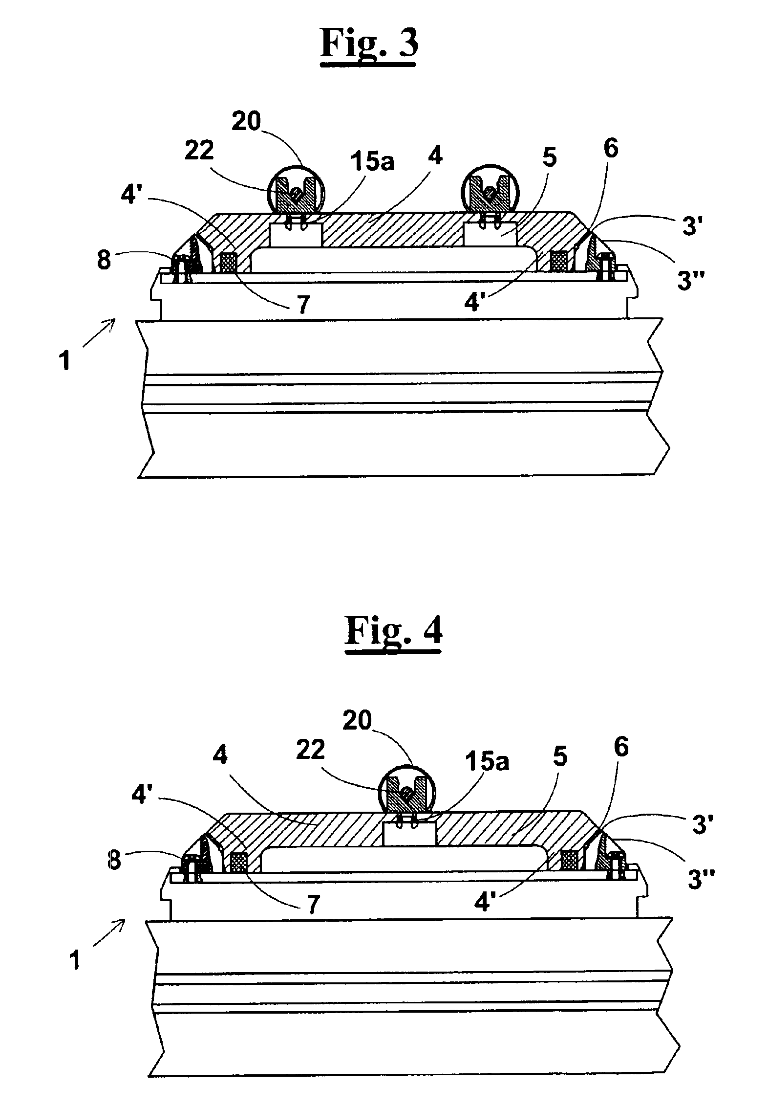
[0040]With reference to FIGS. 1 and 2, a workpiece carrier for automatic production lines, or pallet 1, comprises a base having a substantially rectangular shape and made of light material, for example resin, reinforced by a metal plate 2. To plate 2 are fastened, by means of screws 8 engaging in holes 8′, two reference bars 3. As better shown in FIGS. 5 and 6 reference bars 3 have a first inclined face 3′ and a second inclined face 3″ directed towards opposite sides.

[0041]Always with reference to FIGS. 1 and 2, on reference bars 3 of pallet 1 are arranged two bridges 4 to which two couples of support elements 15 and 16 are connected for workpieces 20, in particular armatures for electric motors.

[0042]Support elements 15 and 16 have V-cross section suitable for supporting portions 22 and 22′ of the shaft of an armature 20. According to an embodiment, as shown in FIGS. 5 and 6, support elements 15 that receive the portion 22 of the shaft are smaller than support elements 16, suitable...


PUM


Abstract

A workpiece carrier for automatic production lines, or pallet (1), having at least a couple of support elements (15,16) for workpieces (20), held by two reference bars (3), fixed to the pallet (1), and by two fastening bridges (4) of orthogonal to the bars (3). The bridges (4) have a central portion, on which the support elements are connected (15, 16), and two ends (4′), suitable for a positive engagement (3′, 6) with the bars (3). The distance between the support elements (15,16) is adjustable raising one of the bridges (4), moving it to another position and lowering it again for completing the positive engagement (3′, 6) with the bars (3) in the new position.

Description

CROSS REFERENCE TO RELATED APPLICATIONS[0001]This non-provisional patent claims priority under 35 U.S.C. §119 to European Patent Application No. EP 02425220.7, which application was filed on Apr. 10, 2002.FIELD OF THE INVENTION[0002]The present invention relates to an equipment for automatic production lines and more precisely it relates to a workpiece carrier, or pallet, with variable distance support members for holding workpieces of different size through such lines. Furthermore, the invention relates to a method for automatic adjustment of the distance between the supports.BACKGROUND OF THE INVENTION[0003]Automatic production lines are known where the workpieces are arranged on workpiece carriers, known in the field as pallets and hereinafter thus indicated, which hold them and carry them through one or several workstations. An example of workpieces is an armature for an electric motor.[0004]More precisely, each pallet, that is initially located in a station of inlet for receivi...

Claims


Application Information

Patent Timeline
IPC IPC(8): B23Q16/00B23Q16/02B23Q7/14H02K15/00
CPCB23Q7/1426B23Q16/022H02K15/0006
Inventor PONZIO, MASSIMOCORBINELLI, RUBINO
Owner ATOP SPA
Learn More