Fluiid pressure striking device

a technology of fluid pressure and hitting device, which is applied in the field of fluid pressure hitting device, can solve the problems of failure of liquid pressure hitting device, reducing the durability of the first chamber and/or the piston, and affecting the accuracy of the hitting force applied to the chisel by the piston, so as to achieve more accurate relaxation, reduce the effect of cavitation and increase the hitting for

Pending Publication Date: 2022-01-27
TEISAKU
View PDF5 Cites 0 Cited by
  • Summary
  • Abstract
  • Description
  • Claims
  • Application Information

AI Technical Summary

Benefits of technology

[0010]In the second aspect of the present disclosure, the fluid supply portion may include the second chamber. In this aspect, since the second chamber is in the vicinity of the first chamber, fluid can be more quickly supplied to the first chamber. Thus, it becomes easier to relax the low pressure state of the first chamber of when the piston hits the chisel. In this way, the occurrence of cavitation can be further suppressed.
[0018]In the eighth aspect of the present disclosure, the third chamber may always be in a high fluid pressure state. In this aspect, since the third chamber is always in a high fluid pressure state, the hitting force applied to the chisel by the piston can be increased. Thus, the piston may receive a stronger repulsive force from the chisel, thereby sliding to the other axial end side of the cylinder to a greater extend. Accordingly, the first chamber tends to enter into a lower pressure state. Thus, when the third chamber is always in a high fluid pressure state, the frequency of cavitation is higher. However, according to the above configuration, the flow path is formed so as to supply fluid from the fluid supply portion to the first chamber. This allows for relaxing the low pressure state of the first chamber when the piston hits the chisel. Further, it is possible to suppress the frequency of cavitation, peculiar to the case where the third chamber is always in a high fluid pressure state.

Problems solved by technology

When the bubbles in the liquid burst, erosion of the fluid pressure hitting device may occur.
Cavitation and erosion can lower the durability of the first chamber and / or the piston.
This can cause the failure of a liquid pressure hitting device, such as due to leakage of liquid from the first chamber.

Method used


Image

  • Fluiid pressure striking device
  • Fluiid pressure striking device
  • Fluiid pressure striking device

Examples


Embodiment Construction

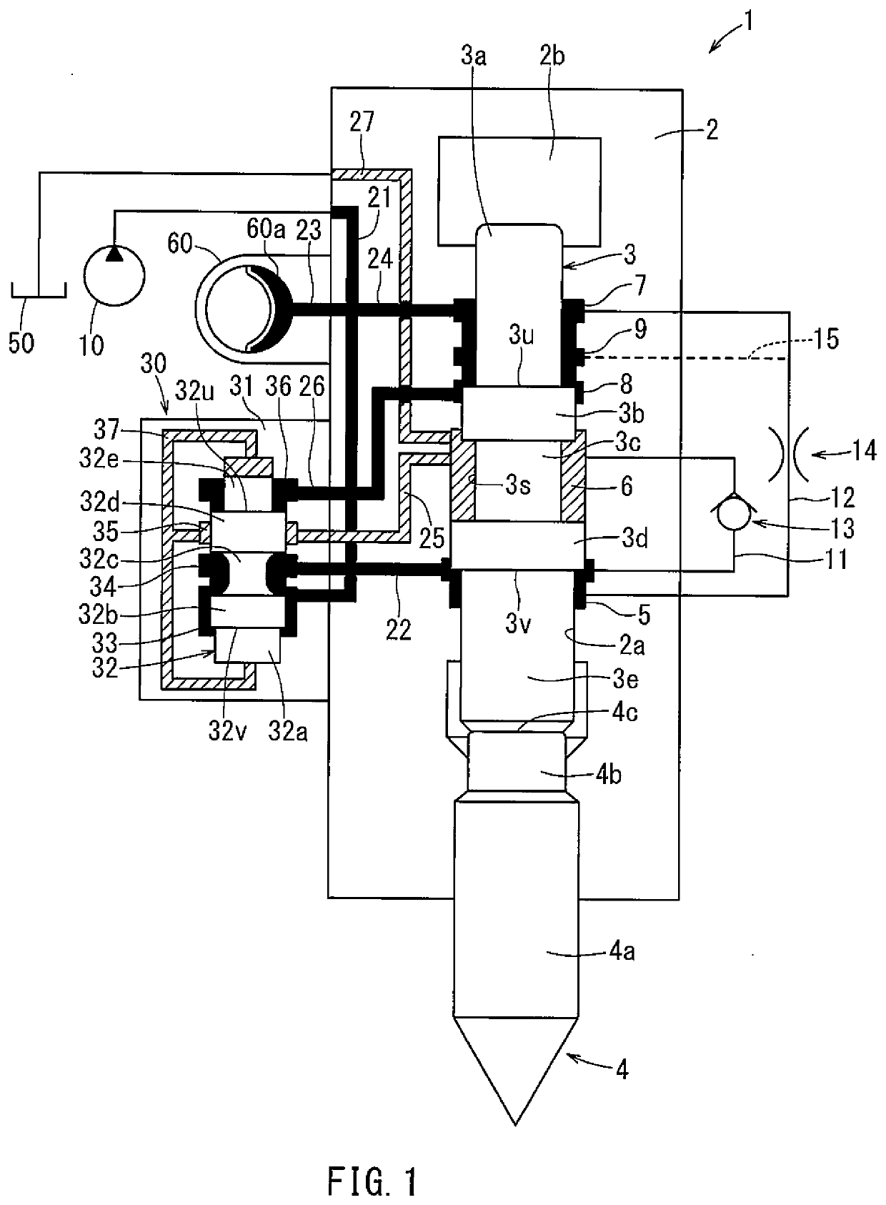
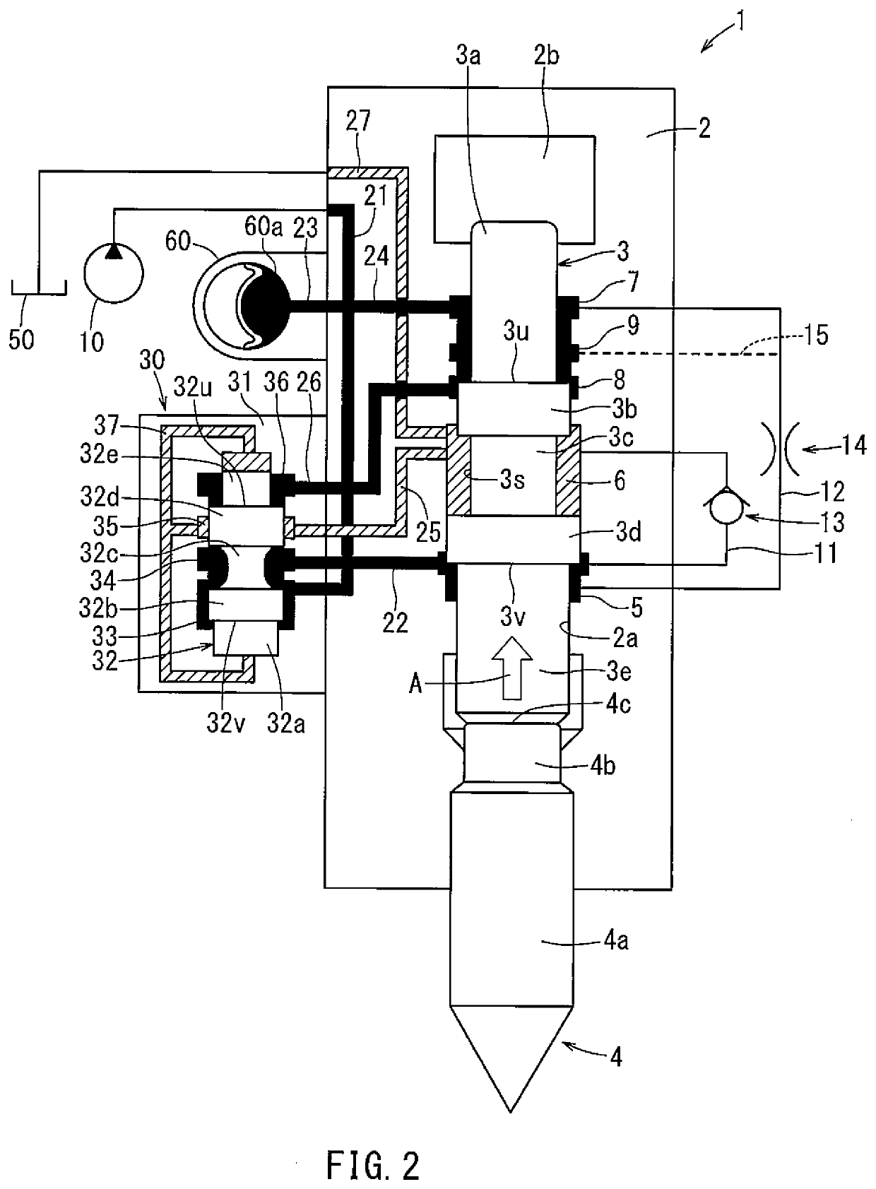
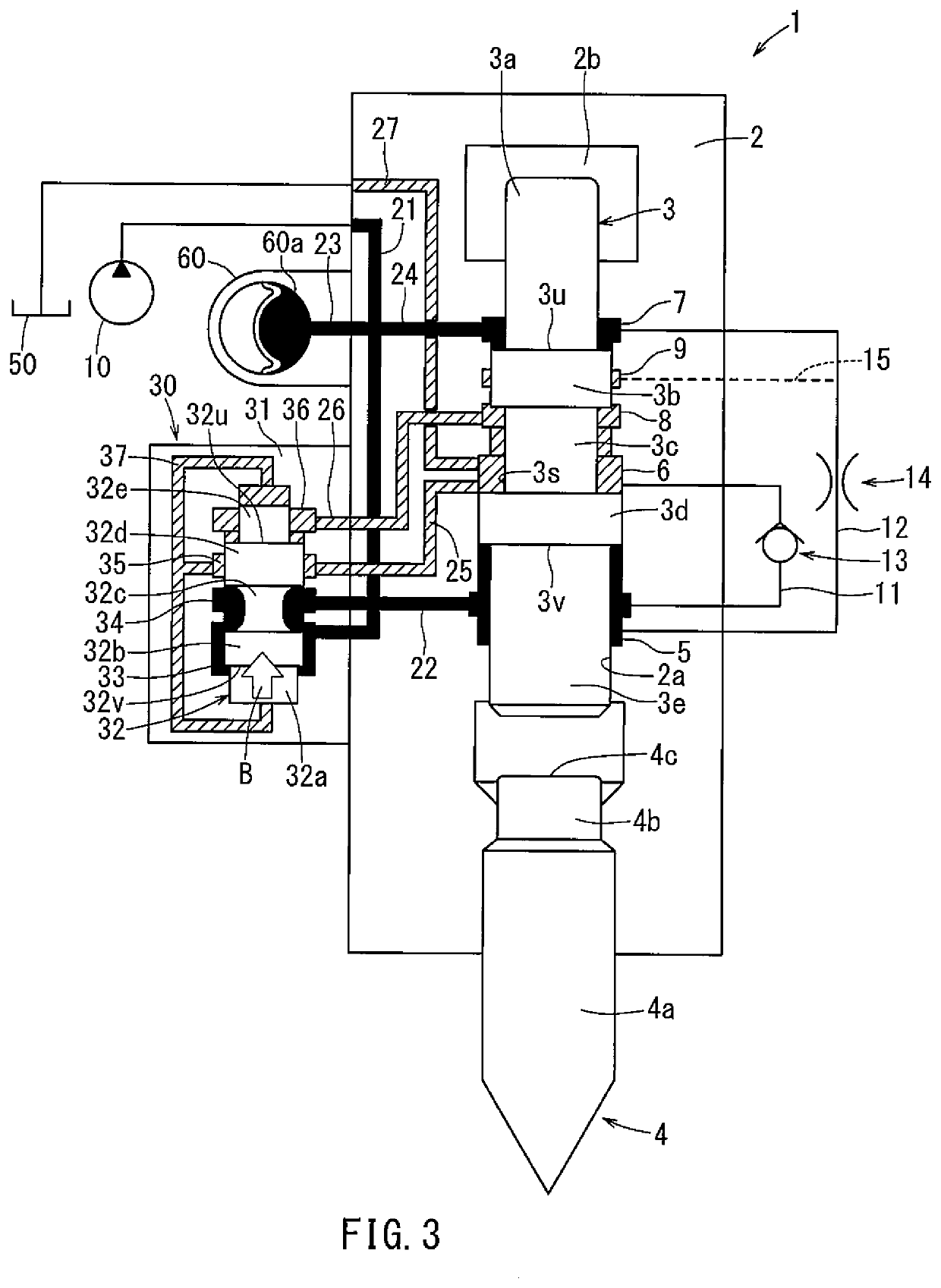
[0067]Hereinafter, embodiments will be further described with reference to first to third examples and a comparative example shown in FIGS. 6 to 9. In the first example, only the first flow path 11 (and the check valve 13) of the fluid pressure hitting device 1 shown in FIG. 1 described above is provided; the second flow path 12 (and the throttle portion 14) is not provided. In the first example, a fluid pressure in the first chamber 5 and a gas pressure in the gas chamber 2b were determined. The results of the first example are shown in FIG. 6. In the graph of FIG. 6, X indicates the gas pressure in the gas chamber 2b. Y indicates the fluid pressure in the first chamber 5. H indicates a moment when the piston 3 hit the chisel 4. V indicates a moment when the state of the fluid pressure hitting device 1 shifts from that shown in FIG. 5 to that shown in FIG. 2. At this moment, the valve high pressure chamber 33 and the valve reversing chamber 34 become in communication with each othe...


PUM


Abstract

A fluid pressure hitting device comprises a piston inserted in a cylinder, a chisel, and a first, second, and third chambers. The chisel is fitted in the cylinder such that a part of the chisel projects from one axial end of the cylinder and is configured to further project from that axial end due to being hit by the piston as the piston slides toward the one axial end. The first through third chambers are partitioned by an inner peripheral surface of the cylinder and an outer peripheral surface of the piston. The first through third chambers are arranged in the axial direction in order fluid the one axial end to another axial end of the cylinder. A flow path is configured to supply fluid from a fluid supply portion when the piston hits the chisel, to the first chamber.

Description

CROSS-REFERENCE TO RELATED APPLICATIONS[0001]The present application is a U.S. National Phase entry of, and claims priority to, PCT Application No. PCT / JP2019 / 043632, filed Nov. 7, 2019, which claims priority to Japanese Patent Application No. 2018-219081, filed Nov. 22, 2018, all of which are incorporated herein by reference in their entireties for all purposes.FIELD OF THE INVENTION[0002]The present disclosure relates to a fluid pressure hitting device.BACKGROUND OF THE INVENTION[0003]A fluid pressure hitting device can be used in the crushing work of concrete, rock, etc. A fluid pressure hitting device has a cylindrical cylinder, a piston fitted in the cylinder, and a rod-shaped chisel. The piston is slidable in the cylinder in an axial direction of the cylinder. The chisel may be fitted in the cylinder so that a part of the chisel projects from one axial end of the cylinder. As the piston slides in the axial direction in the cylinder toward the one axial end in the axial directi...

Claims


Application Information

Patent Timeline
Patent Type & Authority Applications(United States)
IPC IPC(8): B25D9/14B25D9/18B25D17/02
CPCB25D9/145B25D2209/002B25D17/02B25D9/18
Inventor ITO, MASANORIFUJIMOTO, HIROSHI
Owner TEISAKU
Why Eureka
Try Eureka