

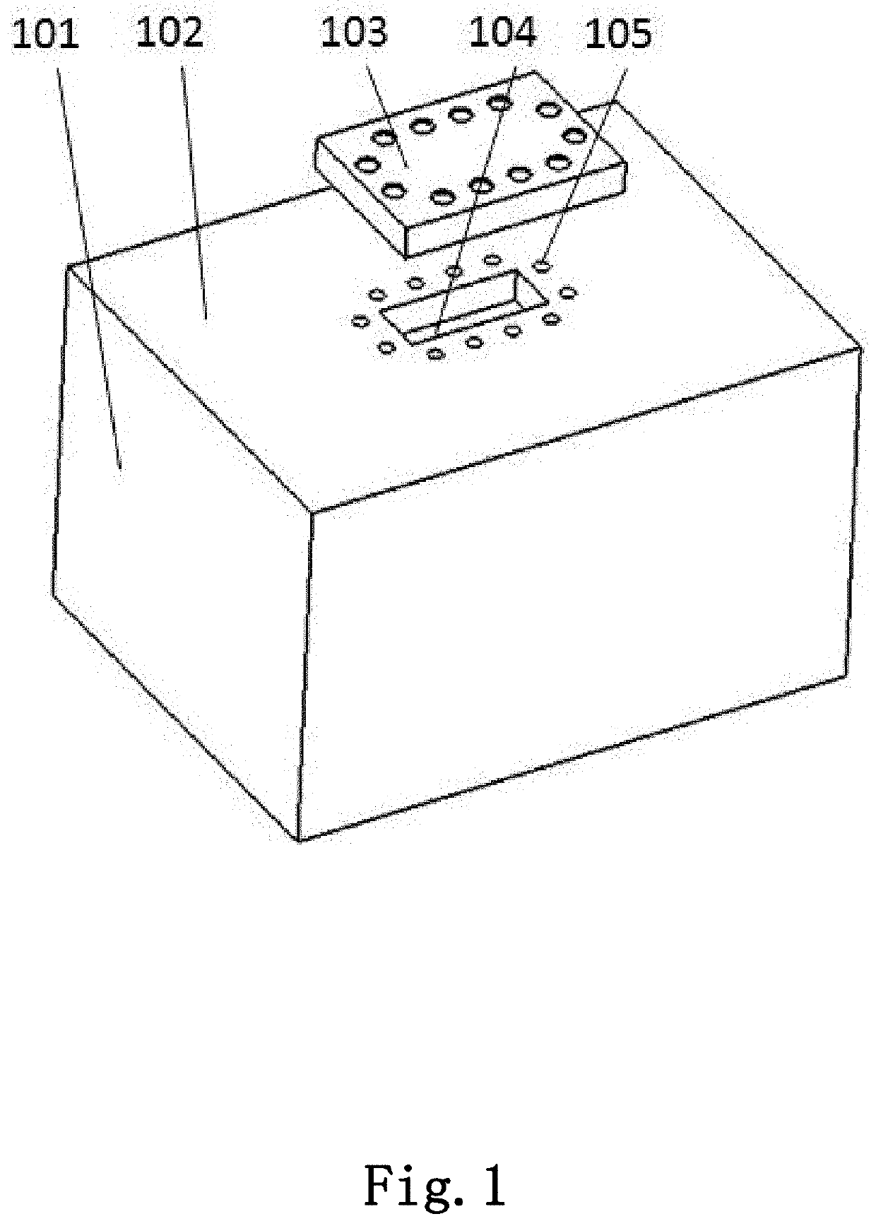
Seal gasket for flat plate structure and sealing structure thereof
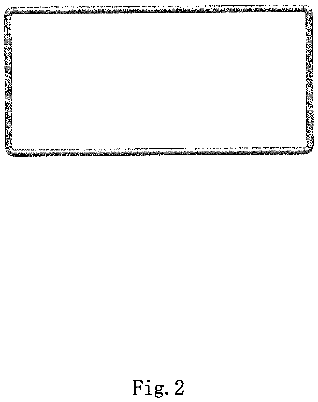
a flat plate and gasket technology, applied in the direction of engine seals, mechanical devices, engine components, etc., can solve the problems of difficult to fix the seal gasket, the common sealing method using knife-edge flanges and metal gaskets is not suitable for this situation, and the seal gasket shown in fig. 2 has some limitations, etc., to achieve accurate positioning, simple and fast implementation process, and convenient disassembly
- Summary
- Abstract
- Description
- Claims
- Application Information
AI Technical Summary
Benefits of technology
Problems solved by technology
Method used
Image

Examples
Embodiment Construction
[0021]The technical solutions of the present disclosure will be clearly and fully described below with reference to the accompanying drawings. Obviously, the described embodiments are only some of the embodiments of the present disclosure, not all of them. Based on the embodiments of the present disclosure, all other embodiments obtained by those skilled in the art without creative work shall fall within the scope of protection of the present disclosure.
[0022]It should be noted that in the description of the present disclosure, directional or positional relationships indicated by terms such as “center”, “upper”, “lower”, “left”, “right”, “vertical”, “horizontal”, “inner” and “outer” are based on the directional or positional relationships shown in the drawings. They are merely used for the convenience of simplified description of the present disclosure, and do not indicate or imply that the device or element involved must have a specific orientation, or be configured or operated in ...
PUM
| Property | Measurement | Unit |
|---|---|---|
| diameters | aaaaa | aaaaa |
| roughness | aaaaa | aaaaa |
| diameters | aaaaa | aaaaa |
Abstract
Description
Claims
Application Information