

Retaining mechanism for eyewear
- Summary
- Abstract
- Description
- Claims
- Application Information
AI Technical Summary
Benefits of technology
Problems solved by technology
Method used
Image

Examples
Embodiment Construction
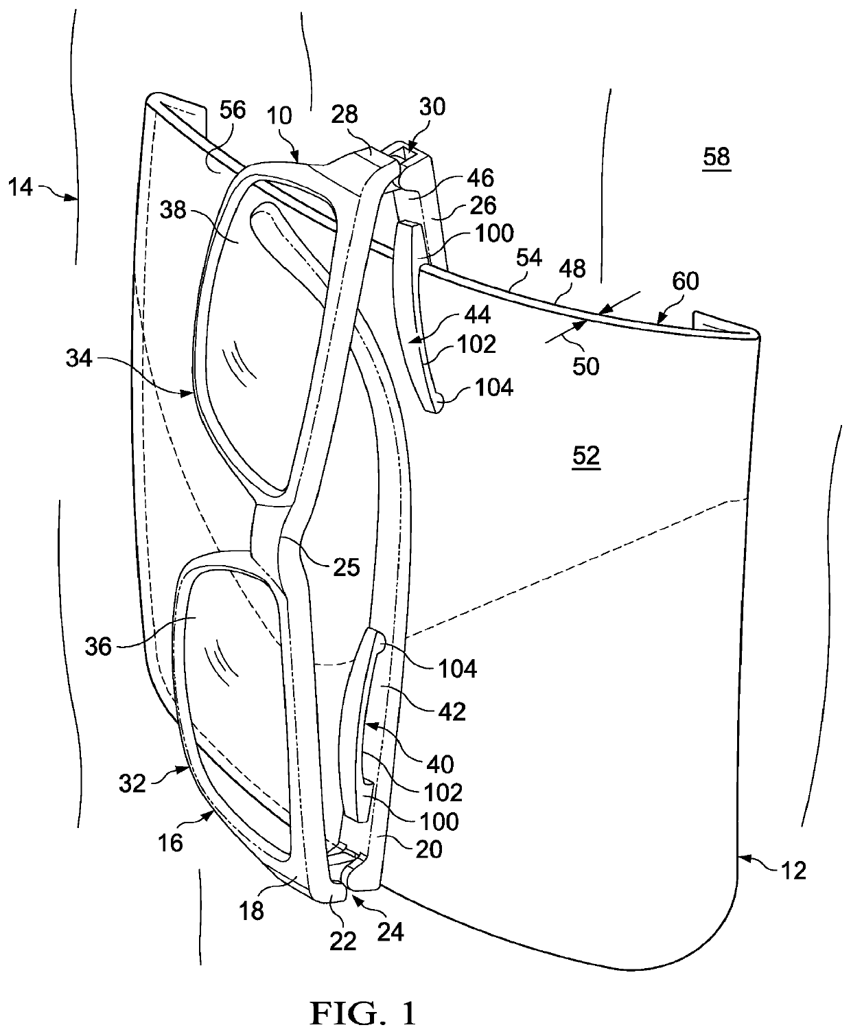
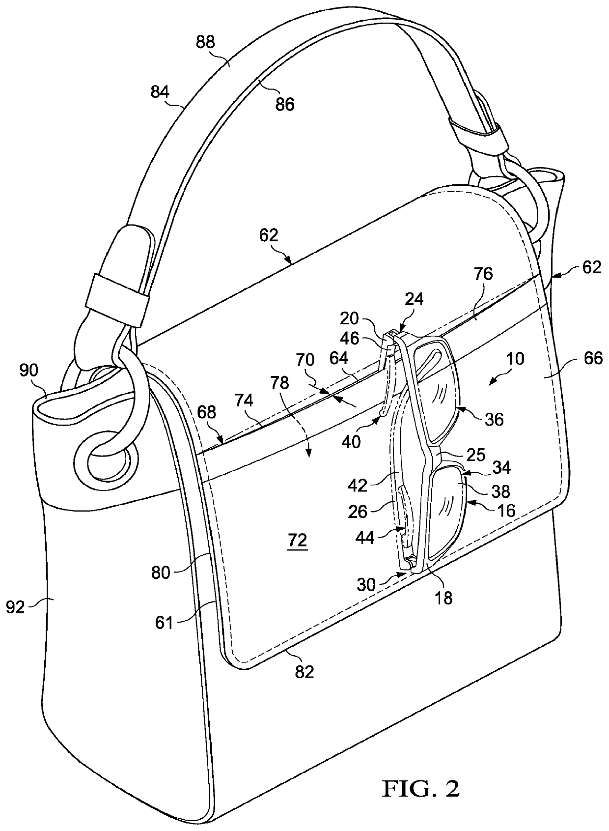
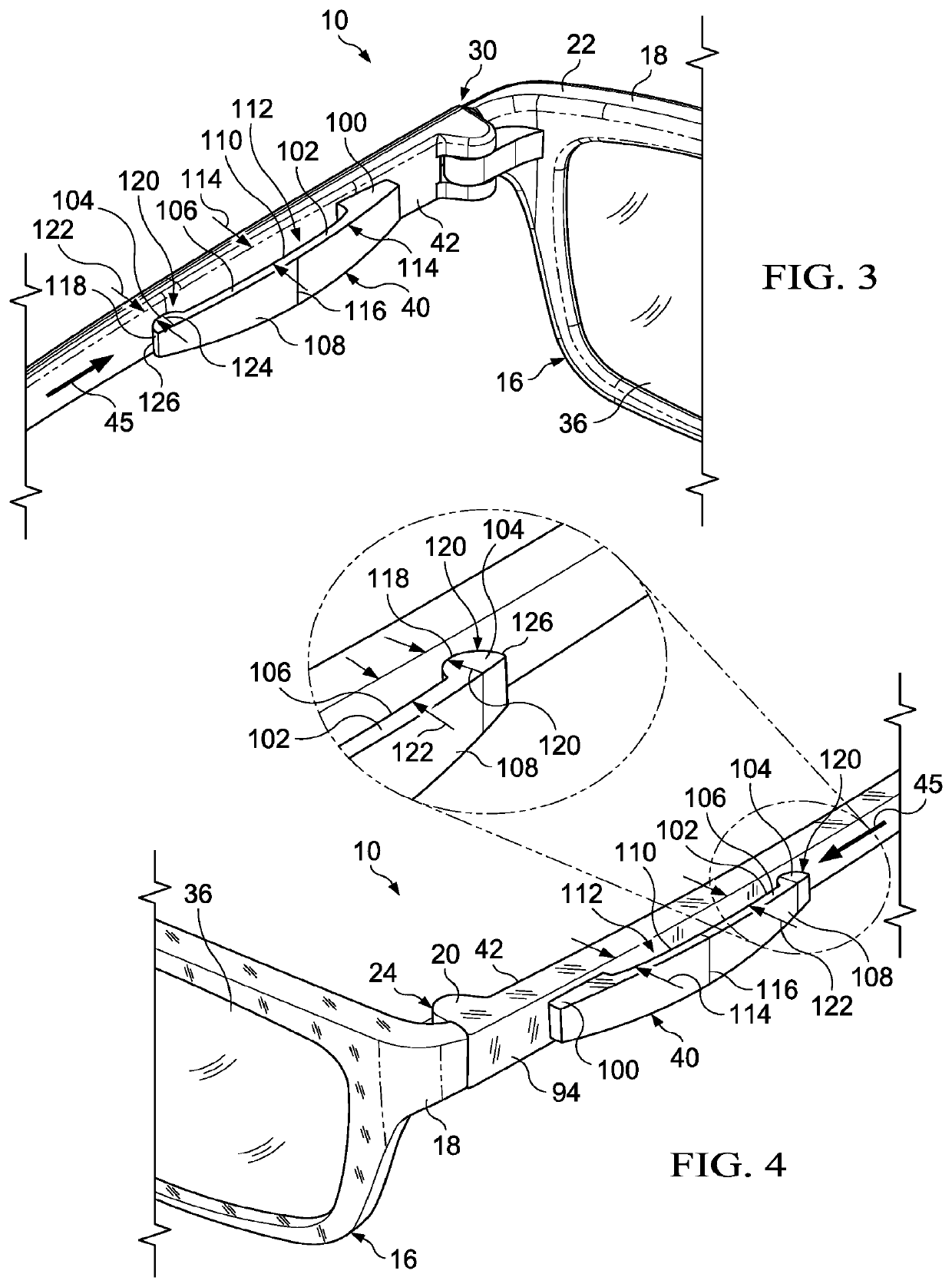
[0037]Referring now to the drawings, and to FIG. 1 in particular, retaining eyewear 10, such as a pair of eyeglasses, protective eyewear, sunglasses, prescription lenses, and so on, in accordance with an exemplary embodiment of the invention, is illustrated attached to the pocket 12 of an article of clothing 14, such as a shirt, blouse, pair of pants, and so on, for securing and carrying the retaining eyewear 10 when not in use with a high confidence level that the eyewear will stay clamped on a shirt pocket or the like or wherever it has been placed when not in use.
[0038]The retaining eyewear 10 preferably includes a retaining frame 16 having a frame front portion 18 with a bridge 25 supported on a nose of a person in a known manner, with a left temple 20 pivotally connected to a left end 22 of the frame front portion 18 via a left hinge joint 24, and a right temple 26 connected to a right end 28 of the frame front portion 18 via a right hinge joint 30. The frame front portion 18 a...
PUM
 Abstract
Description
Claims
Application Information