Eureka AIR delivers breakthrough ideas for toughest innovation challenges, trusted by R&D personnel around the world.

Connector

Active Publication Date: 2022-01-27
YAZAKI CORP
View PDF1 Cites 4 Cited by
  • Summary
  • Abstract
  • Description
  • Claims
  • Application Information

AI Technical Summary

Benefits of technology

The invention is aimed at providing a connector that can reduce the pressure on the conductive component.

Problems solved by technology

Further, as a result of oscillation and drooping of the conductor lead-out area side, the conductive component may be bent from the end of the reinforcing plate on the conductor lead-out area side of the conductive component, so that overload may be applied to the bent part.

Method used


Image

  • Connector
  • Connector
  • Connector

Examples


embodiment

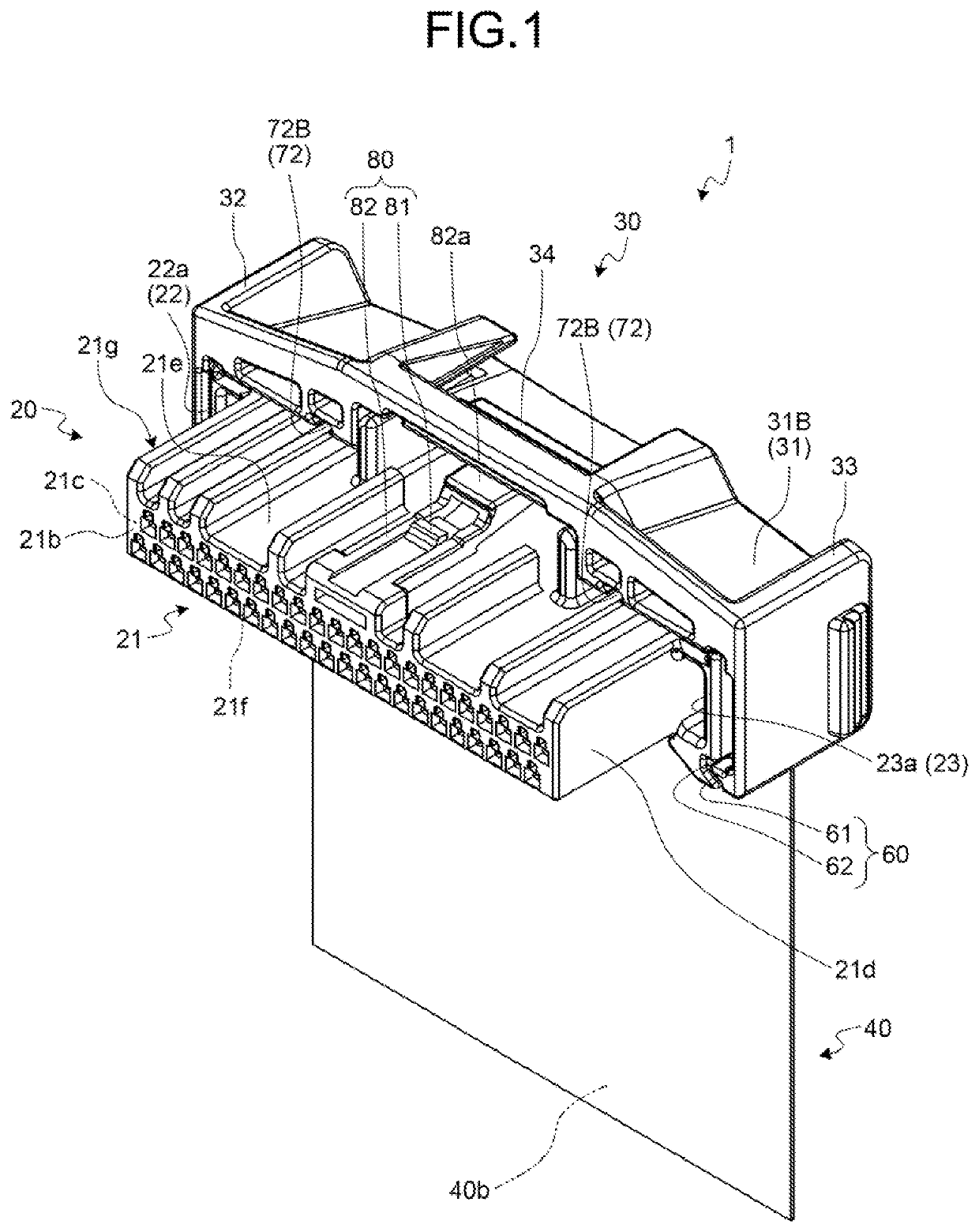
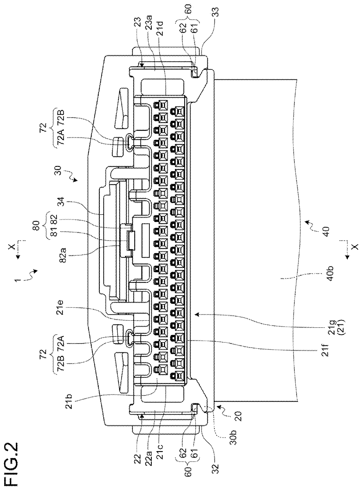
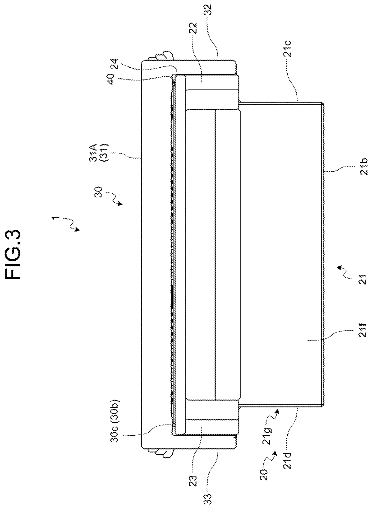
[0025]One embodiment of the connector according to the present invention will be described with reference to FIG. 1 to FIG. 11.

[0026]Reference numeral 1 in FIG. 1 to FIG. 9 indicates the connector of the embodiment. The connector 1 includes: a terminal fitting 10; a housing 20 in which the terminal fitting 10 is accommodated; a cover 30 assembled to the housing 20; and a conductive component 40 that is physically and electrically connected to the terminal fitting 10 in an inner space formed with the housing 20 and the cover 30 in an assembled state, and led out to an outer side from the inner space. Furthermore, the connector 1 includes a reinforcing plate 50 that partially reinforces the conductive component 40.

[0027]The terminal fitting 10 is formed with a conductive material such as metal. For example, the terminal fitting 10 is shaped in a prescribed shape by press molding such as folding work and cutting work performed on a metal plate as a base material. The terminal fitting 1...


PUM


Abstract

A connector includes: a terminal fitting; a housing including a smooth terminal lead-out area where a terminal outlet for projecting a conductor connection part of the terminal fitting on the inner side toward an outer side is provided; a conductive component shaped in a sheet-like form with a conductor and an insulator exhibiting flexibility, the conductive component including a conductor connection area that physically and electrically connects the conductor to the conductor connection part, and a conductor lead-out area led out from the conductor connection area toward a lead-out direction projecting from the housing; and a reinforcing plate shaped in a planar shape with an insulating material, the reinforcing plate being sandwiched between the conductor connection area and the terminal lead-out area. The housing includes a protruded body protruded toward the conductor lead-out area side of the conductive component than a same plane with the terminal lead-out area.

Description

CROSS-REFERENCE TO RELATED APPLICATION(S)[0001]The present application claims priority to and incorporates by reference the entire contents of Japanese Patent Application No. 2020-126060 filed in Japan on Jul. 27, 2020.BACKGROUND OF THE INVENTION1. Field of the Invention[0002]The present invention relates to a connector.2. Description of the Related Art[0003]As conventionally known connectors, there is a type that includes a terminal fitting, a housing in which the terminal fitting is accommodated, and a conductive component that is formed in a sheet-like form having flexibility such as a flexible printed circuit (what is called FPC) to be electrically connected to the terminal fitting. As for the connector, the conductive component includes: a conductor connection area that is physically and electrically connected to a protruded portion of the terminal fitting from the housing; and a conductor lead-out area that is led out from the conductor connection area to be projecting from th...

Claims


Application Information

Patent Timeline
IPC IPC(8): H01R12/77
CPCH01R12/771H01R13/506H01R13/46H01R13/02H01R12/79H01R12/7011H01R12/592
Inventor NAGASAKA, NAOKAZUSAWAIRI, KAORU
Owner YAZAKI CORP
Why Eureka
Eureka Blog
Learn More