Transport container

a technology for transporting containers and containers, applied in domestic refrigerators, refrigeration machines, domestic cooling apparatus, etc., can solve the problems of reducing the efficiency of passive temperature control elements, so as to improve the efficiency of passive temperature control and reduce the weight and/or volume. , the effect of improving the cooling system

Active Publication Date: 2022-02-03
REP IP
View PDF3 Cites 0 Cited by
  • Summary
  • Abstract
  • Description
  • Claims
  • Application Information

AI Technical Summary

Benefits of technology

[0014]The invention therefore aims to provide a transport container of the type mentioned at the outset that has an improved cooling system. In particular, the cooling system is to be improved to the effect that the transport goods can be kept in a predefined temperature range over a longer transport time without changing the weight of the cooling system, or that a weight and / or volume reduction of the cooling system can be achieved without reducing the maximum possible transport time, respectively.
[0040]Particularly preferably, the latent heat accumulator has a phase transition temperature of 3-10° C., in particular 5° C., so that the chamber for the transport goods can be kept in a simple manner in a temperature range of 2-8° C.

Problems solved by technology

However, such passive temperature control elements are depleted as soon as the temperature equalisation with the interior of the transport container is completed.
A disadvantage of latent heat accumulators is the fact that they lose their effect as soon as the entire material has completely gone through the phase change.
The cooling systems existing today often have a large weight in relation to the insulation.
A disadvantage of the cooling system described in WO 02 / 099345 A1 is that cooling no longer takes place as soon as the water is consumed or the saturation of the desiccant is reached.
For large transport containers, however, this is very complex and therefore not appropriate.
Incidentally, a diesel engine would be much less weight efficient.

Method used


Image

  • Transport container
  • Transport container

Examples


Embodiment Construction

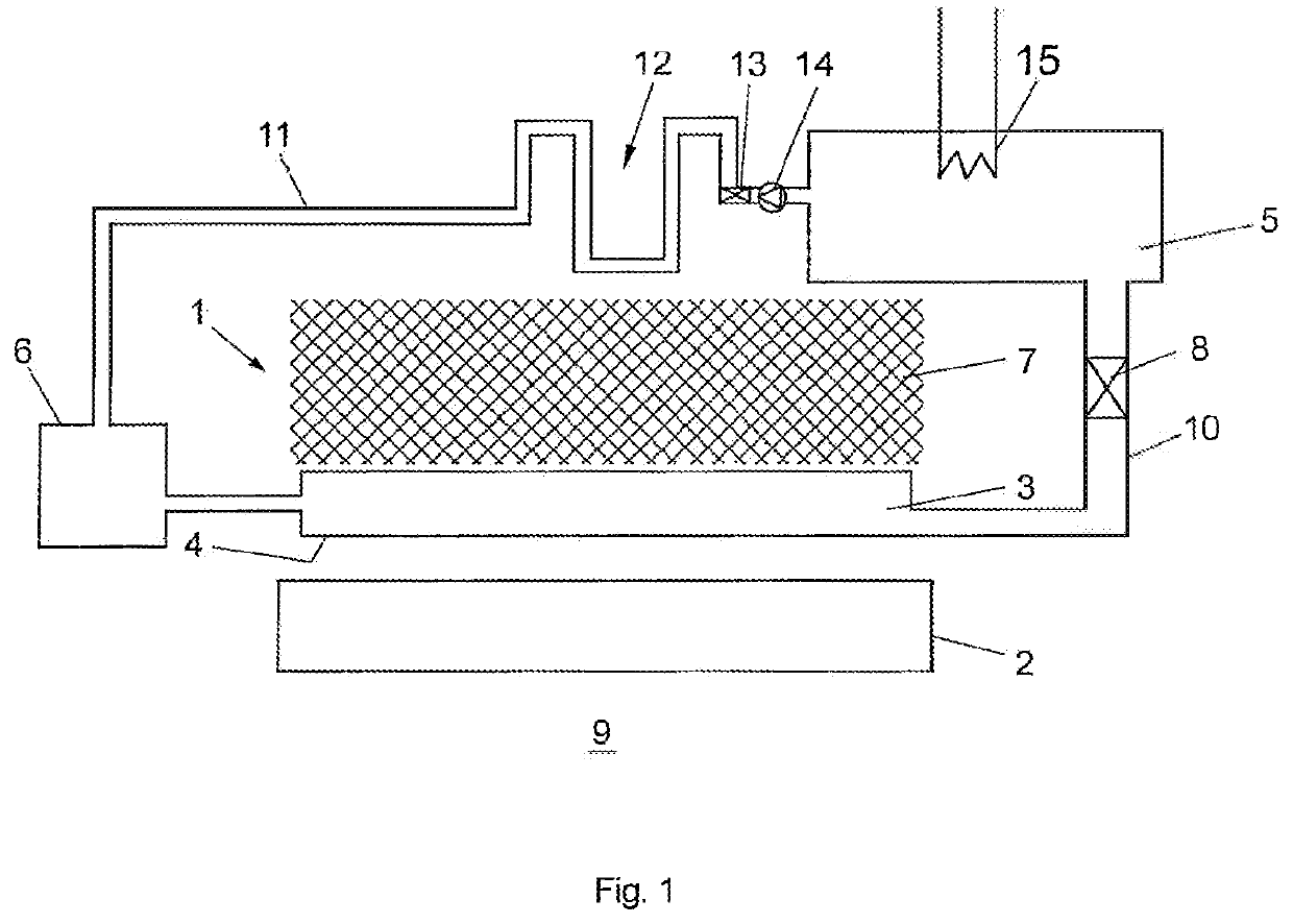
[0046]In FIG. 1, a cooling system is shown, which comprises an evaporative cooling system 1 and a latent heat accumulator 2. The evaporative cooling system 1 comprises an evaporation element 3, which is soaked with a coolant, such as e.g. water, and has a cooling surface 4, and a desiccant 5 for receiving evaporated coolant from the evaporation element 3. To supply the evaporation element 3 with coolant, the same is connected to a reservoir 6. The transport of the evaporated coolant from the evaporation element 3 to the desiccant 5 is performed via a channel 10. The common shell or wall of the evaporation element 3, the channel 10 and the desiccant 5 is gas-tight, so that the relative humidity of the gas atmosphere within the evaporative cooling system 1 can be regulated independently from the environment. The evaporated coolant is absorbed in the desiccant 5, which is e.g. a silica gel.

[0047]In that case the desiccant 5 is located on that side of the evaporative cooling system 1, o...


PUM


Abstract

A transport container for transporting temperature-sensitive transport goods comprising a chamber for receiving the transport goods, a casing enclosing the chamber and at least one cooling element for temperature control of the chamber, wherein the cooling element comprises an evaporation element with a cooling surface, a desiccant for receiving coolant evaporated in the evaporation element and a reservoir for the coolant which is fluidly connectable with the evaporation element. Means are provided for evaporating the coolant stored in the desiccant and the desiccant is connected to the reservoir for transporting the vaporized coolant to the reservoir.

Description

CROSS-REFERENCE TO RELATED APPLICATIONS[0001]This application is a Continuation Application of U.S. Ser. No. 16 / 324,170, filed Feb. 8, 2019, which is the U.S. National Stage of PCT / IB2017 / 000940, filed Aug. 9, 2017, which claims priority to AT A 367 / 2016, filed Aug. 9, 2016. The contents of each of these applications are incorporated herein by reference in their entireties.[0002]The invention relates to a transport container for transporting temperature-sensitive transport goods comprising a chamber for receiving the transport goods, a casing enclosing the chamber and at least one cooling element for temperature control of the chamber, wherein the cooling element comprises:[0003]an evaporation element with a cooling surface,[0004]a desiccant for receiving coolant evaporated in the evaporation element,[0005]a transport path for transporting the evaporated coolant to the desiccant,[0006]a reservoir for the coolant that is fluidly connectable with the evaporation element.[0007]When tra...

Claims


Application Information

Patent Timeline
Patent Type & Authority Applications(United States)
IPC IPC(8): F25D11/00F25B17/08F25D3/08F25D11/02
CPCF25D11/003F25B17/08F25D2331/804F25D11/027F25D2303/08F25D3/08F25D11/00Y02E60/14
Inventor ROS, NICO
Owner REP IP
Why Eureka
Try Eureka