

Backlight module and display device
- Summary
- Abstract
- Description
- Claims
- Application Information
AI Technical Summary
Benefits of technology
Problems solved by technology
Method used
Image

Examples
first embodiment
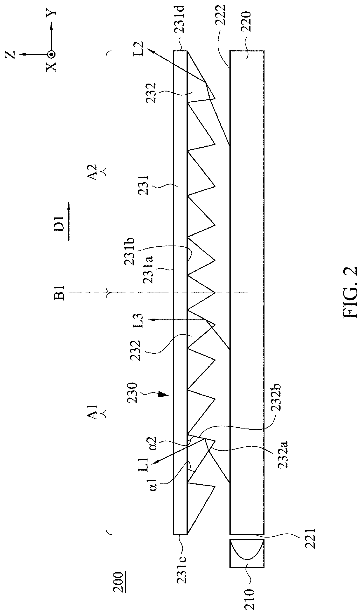
[0027]Referring to FIG. 2, FIG. 2 is a schematic structural diagram showing a backlight module 200 in accordance with the present invention. The backlight module 200 of the present embodiment includes a light source 210, a light-guiding film 220 and an optical film 230. The light-guiding film 220 includes a light-incident surface 221 and a light-emitting surface 222 which is connected to the light-incident surface 221. The light source 210 is disposed adjacent to the light-incident surface 221 to provide light beam to the light-guiding film 220. The optical film 230 is disposed on the light-emitting surface 222 of the light-guiding film 220 to redirect the light beam from the light-guiding film 220 to be emitted in different directions. In one embodiment, the optical film 230 is a turning film.
[0028]As shown in FIG. 2, the optical film 230 includes a main body 231 and plural optical structures 232. The main body 231 has a light-emitting surface 231a, an optical surface 231b, a first...
second embodiment
[0033]In the present disclosure, the optical film may have different designs. Referring to FIG. 5, FIG. 5 is a schematic structural diagram showing a backlight module 300 in accordance with the present invention. The backlight module 300 of the present embodiment includes a light source 310, an optical film 320 and a turning film 330. In the present embodiment, the optical film 320 is a light-guiding film which is used as a light guide plate in a side-type backlight module. The optical film 320 mainly includes a main body 321 and plural optical structures 322. The main body 321 has a light-emitting surface 321a, an optical surface 321b, a first side surface 321c and a second side surface 321d. The light-emitting surface 321a of the main body 321 is opposite to the optical surface 321b, and the first side surface 321c and the second side surface 321d are respectively connected to two opposing side edges of the optical surface 321b. The optical structures 322 are disposed on the optic...
third embodiment
[0036]Referring to FIG. 6, FIG. 6 is a schematic structural diagram showing a backlight module 400 in accordance with the present invention. An optical film 420 of the backlight module 400 of the present disclosure is similar to the optical film 320 shown in FIG. 5, and the main difference therebetween is that optical structures 422 of optical film 420 have different arrangements. As shown in FIG. 6, the backlight module 400 includes a light source 410, an optical film 420 and a turning film 430. The optical film 420 of the present embodiment is a light-guiding film and includes a main body 421 and plural optical structures 422 disposed on the main body 421. The main body 421 has a first side surface 421a, a second side surface 421b, a light-emitting surface 421c and an optical surface 421d, in which the first side surface 421a is a light-incident surface, and the optical structures 422 are disposed on the optical surface 421d. Each of the optical structures 422 has a first surface ...
PUM
 Abstract
Description
Claims
Application Information