Linkage mechanism acting in opposite directions synchronously

Inactive Publication Date: 2022-02-10
ADVANCING DYNAMIC CO LTD
View PDF0 Cites 3 Cited by
  • Summary
  • Abstract
  • Description
  • Claims
  • Application Information

AI Technical Summary

Benefits of technology

[0003]Therefore, a main object of the invention is to provide a linkage mechanism acting in opposite directions synchronously, which utilizes a linkage relationshi

Problems solved by technology

However, because a stroke of the screw assembly for driving the outer frame to displace is very long and the stroke feed is very slow, it takes a l

Method used


Image

  • Linkage mechanism acting in opposite directions synchronously
  • Linkage mechanism acting in opposite directions synchronously
  • Linkage mechanism acting in opposite directions synchronously

Examples


Embodiment Construction

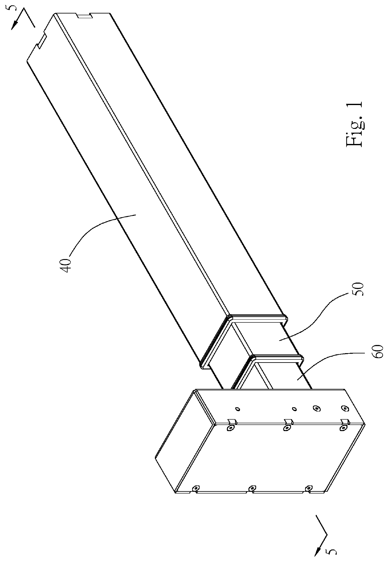
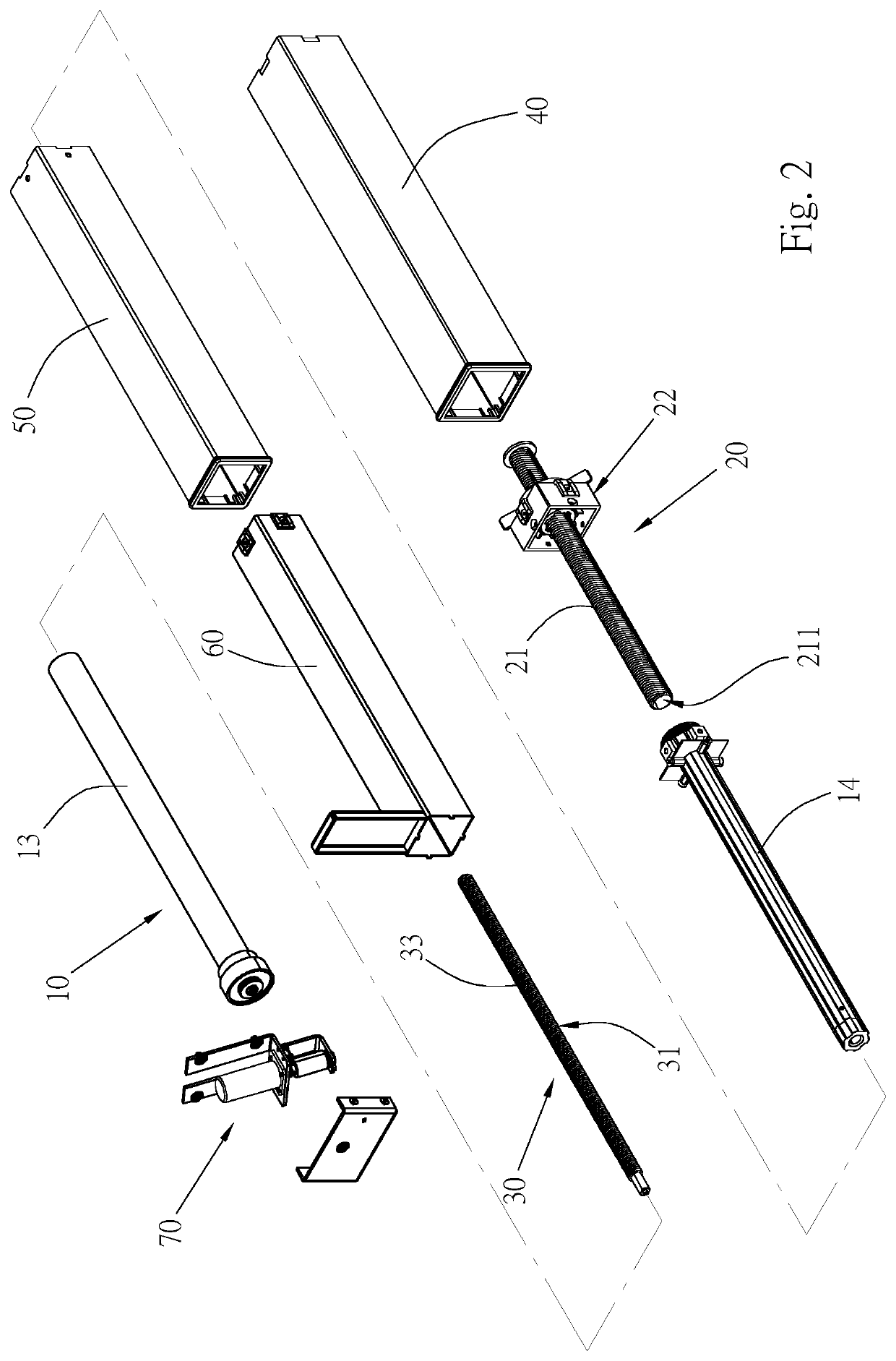
[0023]First of all, please refer to FIGS. 1 to 8. A linkage mechanism acting in opposite directions synchronously provided in a first embodiment of the invention comprises a driving part 10, a first actuating part 20, a second actuating part 30, a first sleeve column 40, a second sleeve column 50, and a third sleeve column 60.

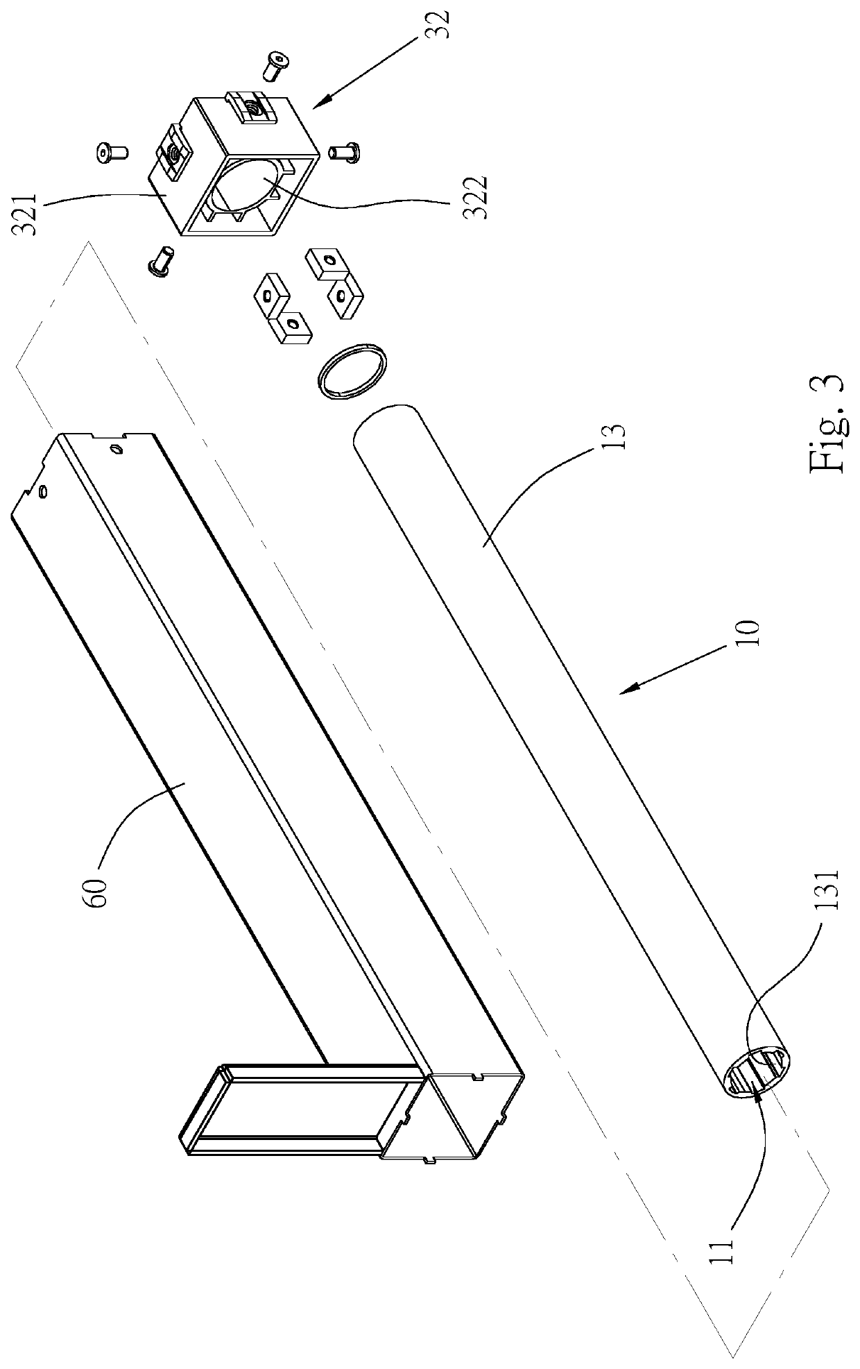
[0024]The driving part 10 has an internal space 11 for accommodating the first actuating part 20 and the second actuating part 30 partially or entirely. When being driven by an external power source 70, the driving part 10 is capable of driving the first actuating part 20 and the second actuating part 30 to displace relatively close to each other in opposite directions or away from each other in opposite directions. Specifically, the driving part 10 has a rotating member 12, an interior of the rotating member 12 forms the internal space 11, when the rotating member 12 is driven by the power source 70 to rotate, the first actuating part 20 and the second actuati...


PUM


Abstract

A linkage mechanism acting in opposite directions synchronously disclosed in the invention comprises a driving part with an internal space and driven by an external power source; a first actuating part disposed in the internal space; and a second actuating part disposed in the internal space. When the first actuating part and the second actuating part are synchronously driven by the driving part, the first actuating part and the second actuating part are relatively displaced close to each other in opposite directions or away from each other in opposite directions. Thereby, with a linkage relationship between the first actuating part and the second actuating part that act in opposite directions, an efficacy of rapid displacement and actions can be achieved.

Description

BACKGROUND OF THE INVENTIONField of Invention[0001]The invention is related to a linkage mechanism, and more particularly to a linkage mechanism acting in opposite directions synchronously.Related Art[0002]Taiwan utility model patent “Single Motor Driven Lifting Table Leg Structure” of No. M590010 is taken as an example for argumentation, which discloses that the leg of the lifting table comprises an inner frame sleeved in an outer frame, and one end thereof is fixed on a base. The inner frame is equipped with a screw assembly, which is driven by a power device and drives the outer frame to displace relative to the inner frame, so that a table plate located above the table leg can ascend and descend. However, because a stroke of the screw assembly for driving the outer frame to displace is very long and the stroke feed is very slow, it takes a long time to drive the table plate to ascend or descend, resulting in the problem of being unable to ascend and descend rapidly and to move q...

Claims


Application Information

Patent Timeline
IPC IPC(8): A47B9/04A47B9/20
CPCA47B9/04A47B2200/0052A47B2009/043A47B9/20
Inventor TSENG, FENG JEN
Owner ADVANCING DYNAMIC CO LTD
Why Eureka
Try Eureka