Tooling splice accommodation for abrasive article production

Pending Publication Date: 2022-02-10
3M INNOVATIVE PROPERTIES CO
View PDF0 Cites 0 Cited by
  • Summary
  • Abstract
  • Description
  • Claims
  • Application Information

AI Technical Summary

Benefits of technology

This patent is about a method and system for producing abrasive articles. The method involves moving a production tool along a path, splicing together the ends of the tool, and adding abrasive particles to a resin coated backing. The system includes a production tool with cavities for holding abrasive particles and a resin coated backing for filling gaps between the abrasive particles. The technical effects of this patent include improved efficiency and accuracy in producing abrasive articles and the ability to produce more complex structures.

Problems solved by technology

This interruption in cavities can result in a gap in the shaped abrasive particles on the abrasive article.

Method used


Image

  • Tooling splice accommodation for abrasive article production
  • Tooling splice accommodation for abrasive article production
  • Tooling splice accommodation for abrasive article production

Examples


first embodiment

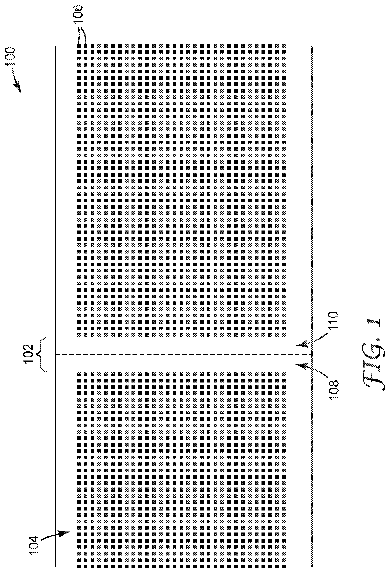
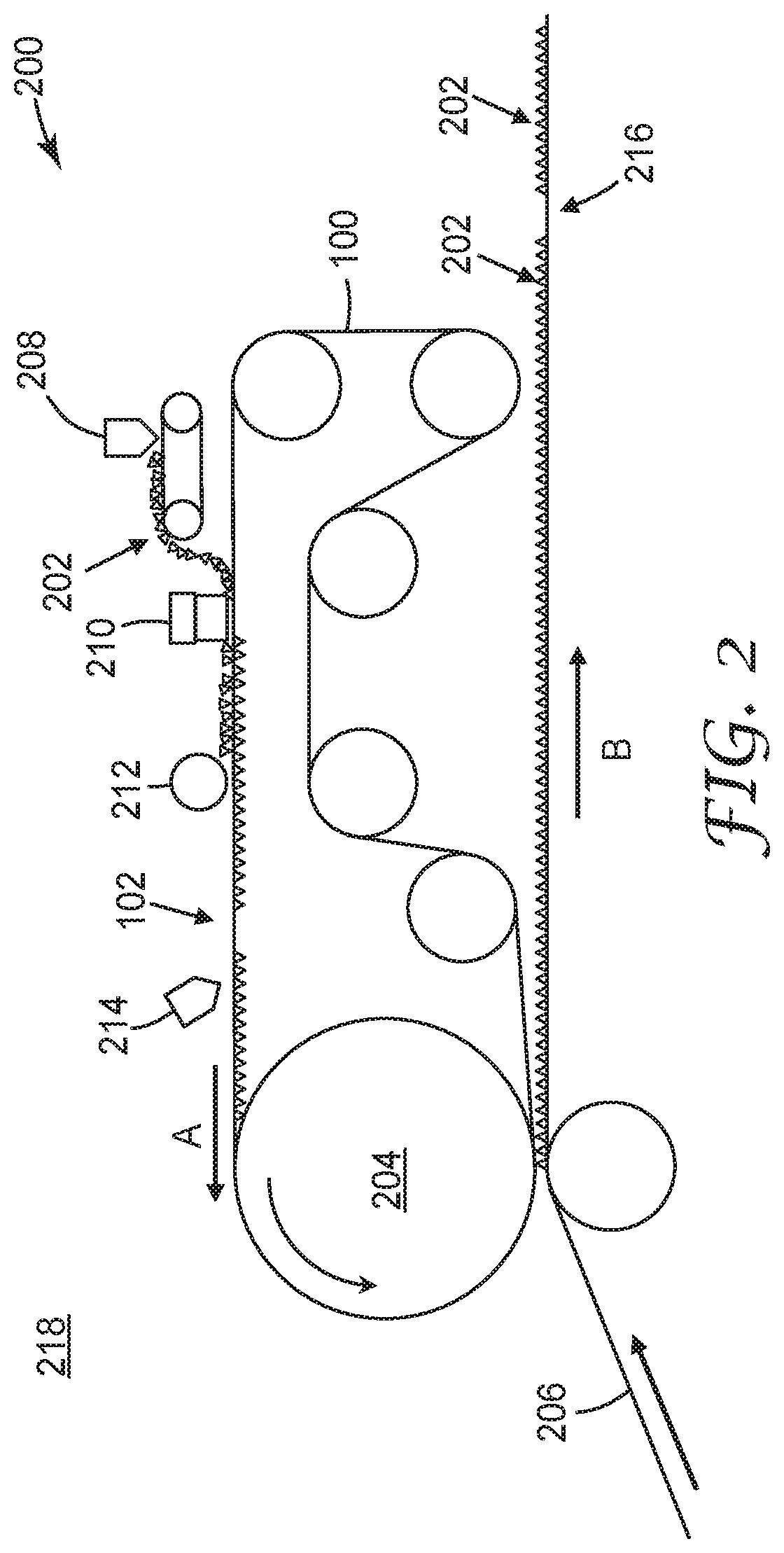
[0068]In a first embodiment, the present disclosure provides a method of producing an abrasive article includes moving a production tool along a first web path, the production tool having a first end and a second end spliced together forming a spliced area. The method also includes providing first shaped abrasive particles to a plurality of cavities formed in a dispensing surface of the production tool, and moving a resin coated backing along a second web path. The method also includes dispensing the first shaped abrasive particles from the plurality of cavities to the resin coated backing, and dispensing second shaped abrasive particles to the resin coated backing into gaps in the first shaped abrasive particles caused by an absence of the plurality of cavities in the spliced area.

[0069]In a second embodiment, the present disclosure provides a method according to the first embodiment, wherein the second shaped abrasive particles comprise at least one magnetic material, and wherein ...

seventh embodiment

[0074]In a seventh embodiment, the present disclosure provides a method according to the, a method of producing an abrasive article includes splicing a first end of a production tool to a second end of the production tool. The production tool includes a plurality of first cavities. The method also includes forming a plurality of second cavities in the spliced area, providing shaped abrasive particles to the plurality of first cavities and the plurality of second cavities, and dispensing the shaped abrasive particles from the plurality of first cavities and the plurality of second cavities to a resin coated backing.

[0075]In an eighth embodiment, the present disclosure provides a method according to the seventh embodiment, a wherein the plurality of second cavities are formed in the spliced area during the splicing of the first end of the production tool to the second end of the production tool.

[0076]In a ninth embodiment, the present disclosure provides a method according to the seve...

tenth embodiment

[0077]In a tenth embodiment, the present disclosure provides a system for producing an abrasive article includes a production tool and a resin coated backing. The production tool includes a first end and a second end spliced together to form a spliced area. The production tool also includes a dispensing surface that includes a plurality of cavities formed between the first end and the second end and configured to receive and hold first shaped abrasive particles. The resin coated backing is configured to receive the first shaped abrasive particles from the dispensing surface of the production tool and is configured to receive second shaped abrasive particles to fill gaps in the first shaped abrasive particles caused by an absence of the plurality of cavities in the spliced area.

[0078]In an eleventh embodiment, the present disclosure provides a system according to the tenth embodiment, further comprising a dispensing apparatus positioned to dispense the second shaped abrasive particle...


PUM


Abstract

A system and method for producing an abrasive article includes a production tool configured to provide shaped abrasive particles to a resin coated backing. A first end and a second end of the production tool are spliced together to form a spliced area. The production tool includes a dispensing surface that includes a plurality of cavities formed between the first end and the second end and configured to receive and hold the shaped abrasive particles. The resin coated backing is configured to receive the shaped abrasive particles from the dispensing surface of the production tool and configured to receive further shaped abrasive particles to fill gaps in the shaped abrasive particles caused by an absence of the plurality of cavities in the spliced area.

Description

BACKGROUND[0001]The present invention relates generally to abrasive articles, and in particular to preventing gaps in abrasive particles created by gaps in cavities of a production tool.[0002]Abrasive articles can be produced using a production tool that includes cavities configured to deliver shaped abrasive particles to a resin coated backing. The cavities can be positioned on the tooling to create a desired pattern of shaped particles on the abrasive article. In some examples, the production tool can be configured to form an endless belt. In making the endless belt, two ends of a production tool can be spliced together, destroying or otherwise interrupting the cavities of the production tool. This interruption in cavities can result in a gap in the shaped abrasive particles on the abrasive article.SUMMARY OF THE DISCLOSURE[0003]In one aspect of the present disclosure, a method of producing an abrasive article includes moving a production tool along a first web path, the productio...

Claims


Application Information

Patent Timeline
IPC IPC(8): B24D11/00B24D11/06B24D18/00B24D3/28
CPCB24D11/005B24D3/28B24D18/0072B24D11/06B24D11/001
Inventor NELSON, THOMAS J.NIENABER, AARON K.ECKEL, JOSEPH B.HAWKINS, ANN M.KOENIG, AMELIA W.
Owner 3M INNOVATIVE PROPERTIES CO
Why Eureka
Try Eureka