Flooring panel

a technology of floor panels and panels, applied in the field of panels, can solve the problems of high production costs, high production costs, and difficult to meet the needs of customers, and achieve the effect of economic benefits

Inactive Publication Date: 2005-10-27
KRONOTEC
View PDF22 Cites 219 Cited by
  • Summary
  • Abstract
  • Description
  • Claims
  • Application Information

AI Technical Summary

Benefits of technology

[0005] An object of the invention is to provide an improved panel with respect t...

Problems solved by technology

A method of this type is very expensive and requires extremely precise work, since the chamfers are very narrow.
The production costs are high due to the correspondingly slow...

Method used


Image

  • Flooring panel
  • Flooring panel

Examples


Embodiment Construction

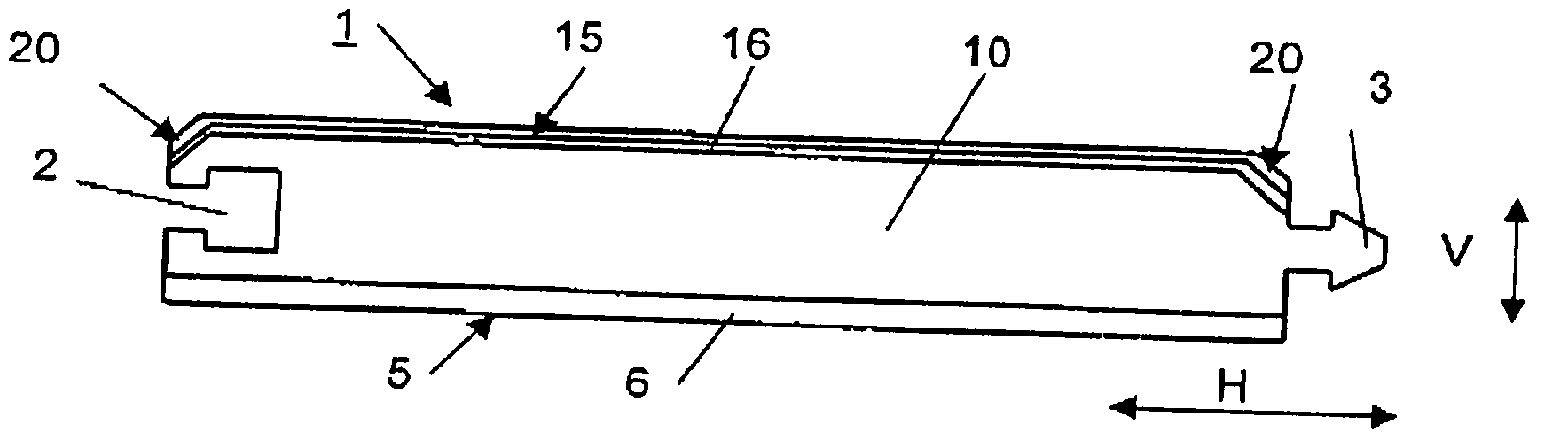
[0013]FIG. 1 shows a panel 1 in a cross-sectional view which is coated on an upper side 15 with a decorative layer 16 and on an under side 5 with a so-called counteracting layer 6. The core 10 of the panel 1 is made of an MDF or HDF material and is compressed at high pressure during production. The decorative layer 16 and the counteracting layer 6 serve as a stabilizing film and give the panel 1 a durable surface. The form-fitting elements 2, 3 arranged on the lateral edges are used to lock several panels to one another and lock the panels both in the horizontal direction H and in the vertical direction V. In addition to the embodiment shown, laying profiles or pivot profiles can also be available on the lateral edges.

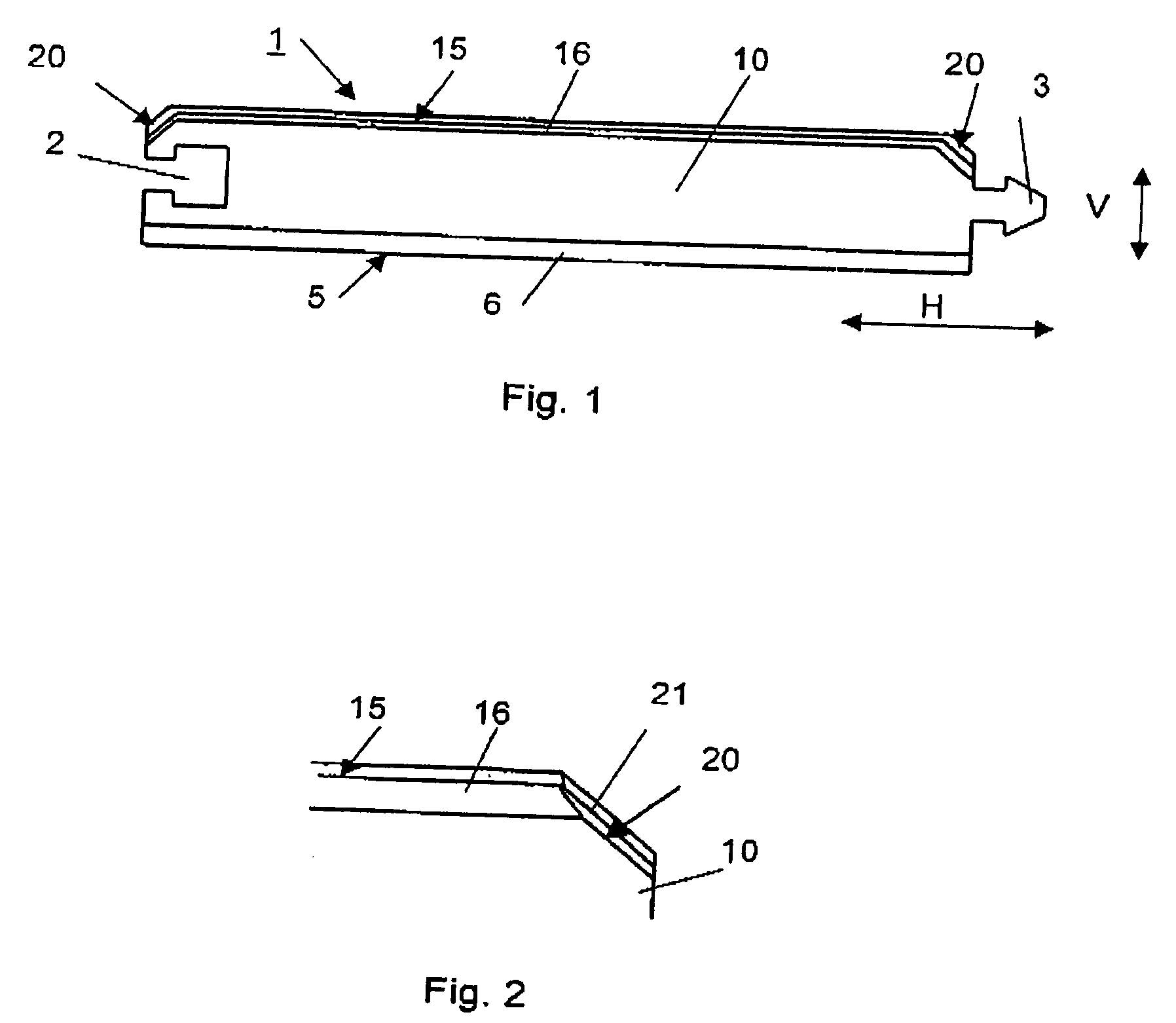
[0014] Alternatively to the use of fiberboards as core 10, OSB materials, chipboard or laminated wood can be used. Starting from the upper side 15, one chamfer 20 each is milled out on both lateral edges, which chamfers in the locked state form a V-shaped vertical joi...


PUM

PropertyMeasurementUnit
Pressureaaaaaaaaaa
Coloraaaaaaaaaa
Densityaaaaaaaaaa

Abstract

A panel, in particular a flooring panel, of a wood material which is provided with a mechanism for the detachable connection of a least two panels, whereby form-fitting elements for locking in the vertical direction and in the horizontal direction with another panel are embodied on at least one lateral edge of a first panel, whereby a chamfer is embodied on at least one lateral edge starting from an upper side. The chamfer or the form-fitting elements are coated or impregnated with at least one melamine layer.

Description

BACKGROUND OF THE INVENTION [0001] 1. Field of the Invention [0002] The invention relates to a panel, in particular a flooring panel, of a wood material which is provided with means for the detachable connection of a least two panels. Form-fitting elements for locking in the vertical direction and in the horizontal direction with another panel are embodied on at least one lateral edge of a first panel, whereby a chamfer is embodied on at least one lateral edge starting from an upper side of the panel. [0003] 2. Discussion of Background Information [0004] A panel is known from WO 01 / 96688 A1. In the conventional art, the chamfer produced by milling is either left untreated or is covered by a decorative strip which is either laminated onto it or adhered to it. A method of this type is very expensive and requires extremely precise work, since the chamfers are very narrow. The production costs are high due to the correspondingly slower process speeds; likewise, inexact gluing results in...

Claims


Application Information

Patent Timeline
IPC IPC(8): B44C5/04E04F13/10E04F15/02E04F15/04E04F15/10
CPCB44C5/043E04F15/02E04F2201/0153E04F15/04E04F2201/0115E04F15/02033
Inventor HECHT, HENDRIK
Owner KRONOTEC
Why Eureka
Try Eureka