
Interface Tubing for Peristaltic Pump

a technology of interface tubing and peristaltic pump, which is applied in the direction of positive displacement liquid engine, application, catheter, etc., can solve the problems of peristaltic pump electrical noise, and achieve the effect of reducing static charge buildup

Pending Publication Date: 2022-02-17
ST JUDE MEDICAL CARDILOGY DIV INC
View PDF8 Cites 0 Cited by
  • Summary
  • Abstract
  • Description
  • Claims
  • Application Information

AI Technical Summary

Benefits of technology

The patent describes a pump interface tubing for a peristaltic pump that reduces static charge buildup and noise signals during operation. The tubular core is treated with a layer of a different material (such as a second material or an anti-static additive) to prevent static buildup. Additionally, the treatment can also resist abrasion of the tubular core. The technical effects of this include reducing damage to the pump interface tubing and improving the efficiency of the peristaltic pump.

Problems solved by technology

It is known, however, that peristaltic pumps may generate electrical noise that can undesirably couple to an electrogram signal measured by the electrodes on the irrigated electrophysiology catheter, to an electroanatomical visualization, localization and / or position system coupled to a subject, and / or to other diagnostic or therapeutic equipment.

Method used

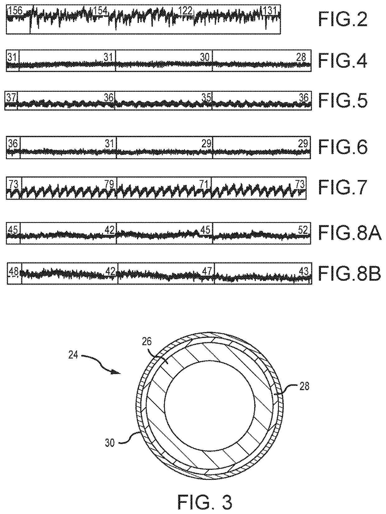

Image

  • Interface Tubing for Peristaltic Pump
  • Interface Tubing for Peristaltic Pump

Examples


Embodiment Construction

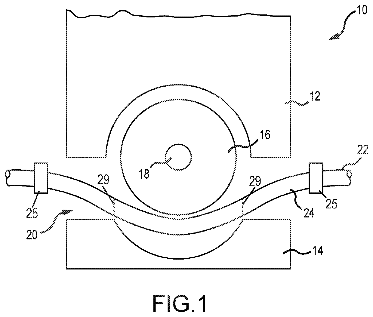
[0029]FIG. 1 depicts a peristaltic pump 10, such as the Cool Point™ Irrigation Pump of St. Jude Medical, Inc. The configuration and operation of peristaltic pump 10 will be familiar to those of ordinary skill in the art (see, e.g., United States patent application publication no. 2007 / 0224063, which is hereby incorporated by reference as though fully set forth herein), such that a detailed explanation thereof is not necessary herein. Instead, only those features of peristaltic pump 10 pertinent to understanding the present disclosure will be described below.

[0030]Peristaltic pump 10 generally includes a housing 12, a clamp 14, and a rotor 16. Rotor 16 includes a plurality of rollers spaced about the circumference of rotor 16 and is mounted to rotate about an axle 18.

[0031]A tubing channel 20 is defined between clamp 14 and rotor 16. Tubing channel 20 accommodates an irrigation tube 22. One end of irrigation tube 22 can be coupled to a suitable reservoir of irrigation fluid, while th...


PUM

PropertyMeasurementUnit
triboelectricaaaaaaaaaa
lengthaaaaaaaaaa
electrical noiseaaaaaaaaaa

Abstract

A pump interface tubing for use in a peristaltic pump includes a tubular core having an outer surface and a treatment on the outer surface. The treatment reduces static charge buildup on the tubular core during operation of the peristaltic pump, and thereby reduces the noise signal that might otherwise undesirably couple to a signal of interest. Treatments include nitrile layers, heat shrink layers, cotton fiber layers, and anti-static sprays.

Description

CROSS-REFERENCE TO RELATED APPLICATIONS[0001]This application is a divisional of U.S. application Ser. No. 15 / 727,847, filed 9 Oct. 2017 (“the '847 application”), now pending, which claims the benefit of U.S. provisional application No. 62 / 416,204, filed 2 Nov. 2016 (“the '204 provisional”). The '847 application and the '204 provisional are hereby incorporated by reference as though fully set forth herein.BACKGROUND[0002]The instant disclosure relates to irrigated electrophysiology catheters. In particular, the present disclosure relates to devices and methods for reducing electrical noise in an irrigated electrophysiology catheter system.[0003]Catheters are used for an ever growing number of medical procedures. To name just a few examples, catheters are used for diagnostic, therapeutic, and ablative procedures. Typically, the physician manipulates the catheter through the patient's vasculature to the intended site, such as a site within the patient's heart. The catheter typically c...

Claims


Application Information

Patent Timeline
Patent Type & Authority Applications(United States)
IPC IPC(8): A61M3/02A61B5/00A61B5/287A61L29/08A61L29/14B29C63/00B29C48/09B29C48/21
CPCA61M3/0279A61B5/7203A61B5/287B29C48/09A61L29/14A61M3/0258B29C63/0069A61L29/08A61M2210/125B29L2031/7496B29K2995/0002B29L2023/225B29C48/21A61M2205/0233A61M2205/0238A61M2205/42A61M2207/00B29L2031/7542F04B43/0072F04B43/12A61L2420/02A61L2420/08B05D1/02B05D1/18
Inventor SCHMIDT, BRIANLEACH, COLEMANKLOOSTERBOER, MICHAELSWANSON, LAWRENCE D.PARSONAGE, EDWARD E.
Owner ST JUDE MEDICAL CARDILOGY DIV INC
Learn More