
Battery electric vehicle supermodule

a battery electric vehicle and supermodule technology, applied in the direction of battery/fuel cell control arrangement, cell components, coupling device connection, etc., can solve the problems of difficult connection of all media and work, difficult area around all electrical components, electric and hybrid electric vehicles, etc., and achieve the effect of low voltage power

Pending Publication Date: 2022-02-17
VOLVO LASTVAGNAR AB
View PDF11 Cites 1 Cited by
  • Summary
  • Abstract
  • Description
  • Claims
  • Application Information

AI Technical Summary

Benefits of technology

The patent text describes an electrical power distribution module for vehicles that includes an upper module and a lower module. The upper module has a circuit board and a temperature control system, while the lower module has a plurality of electrical connectors, isolated busbars, and a plurality of electrical connectors. The isolated busbars are electrically isolated from the surrounding structure and are connected to the electrical connectors. The module is designed to distribute power and ground connections to vehicle components. The temperature control system helps control the temperature of the circuit board. The module is sealed and rated IP 67, and can absorb energy during a collision. The isolated busbars are rated for different voltages and can be connected to the electrical connectors. The technical effects of this design include improved power distribution and temperature control, as well as increased safety and reliability for the vehicle's electrical system.

Problems solved by technology

Currently, vehicles, such as electric and hybrid-electric vehicles, require a lot of components to operate the vehicle.
With the large number of components on a battery electric vehicle (BEV), there is congestion of power, ground, and signal cables, as well as coolant pipes, which makes the area around all of the electrical components very difficult to connect all the media as well as work on them when service is required.

Method used


Image

  • Battery electric vehicle supermodule
  • Battery electric vehicle supermodule
  • Battery electric vehicle supermodule

Examples


Embodiment Construction

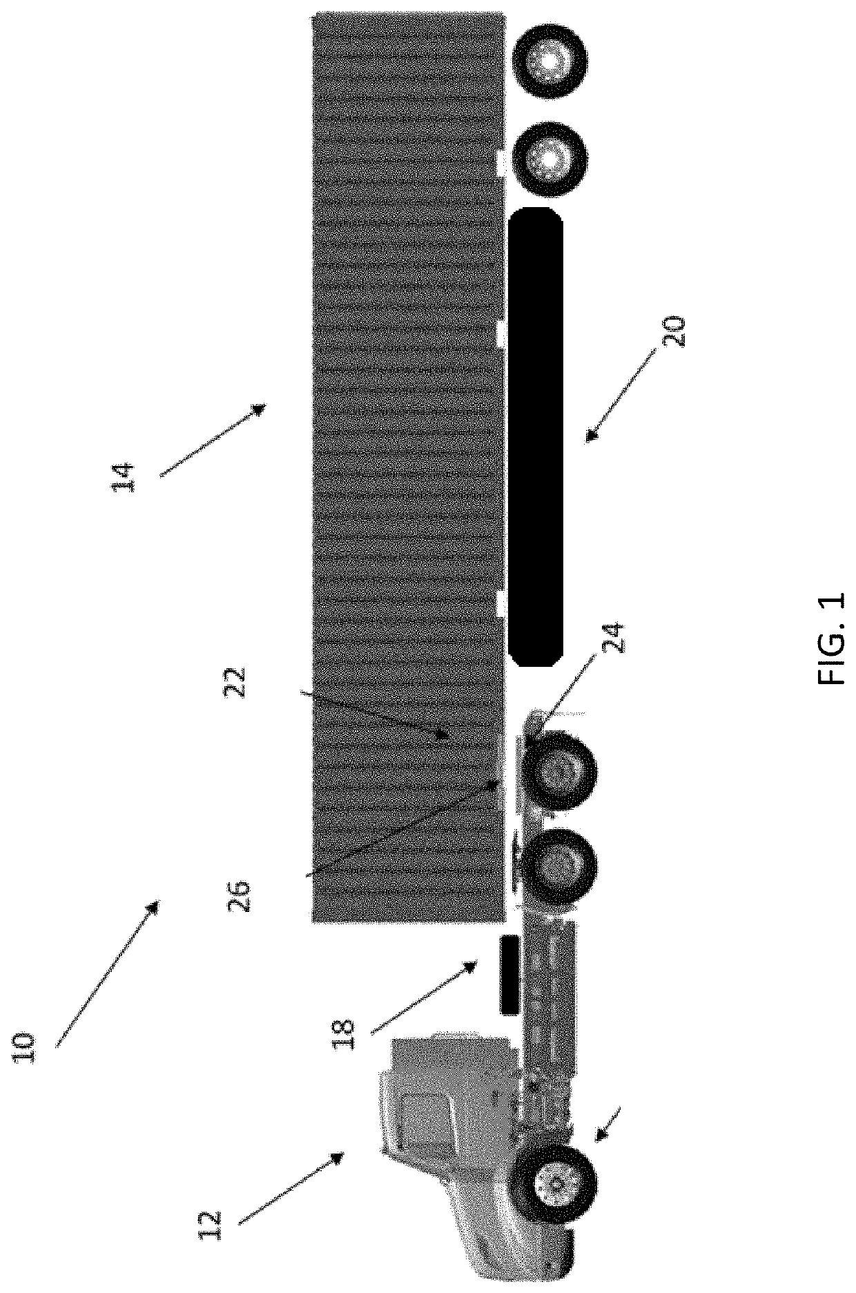
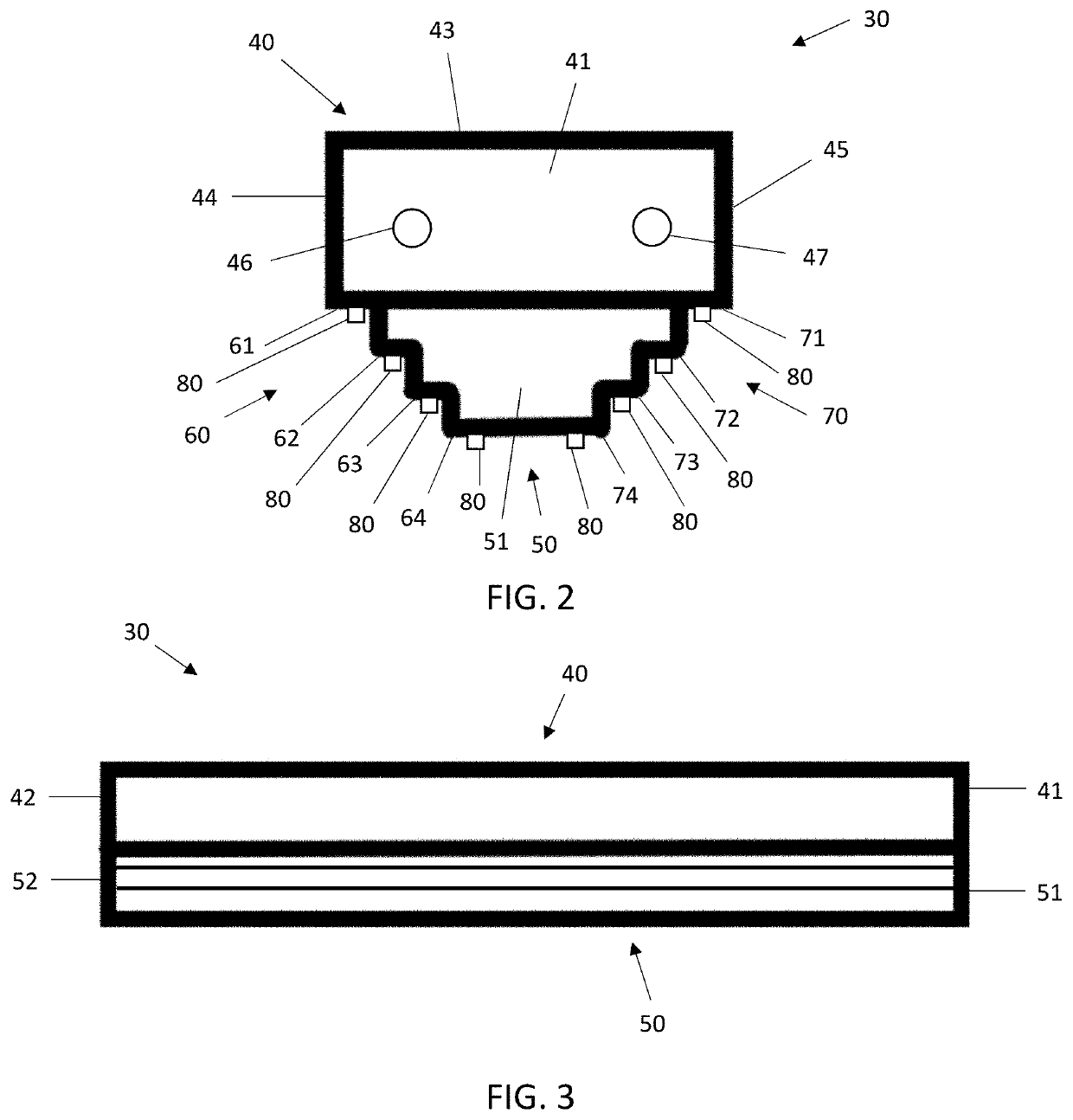
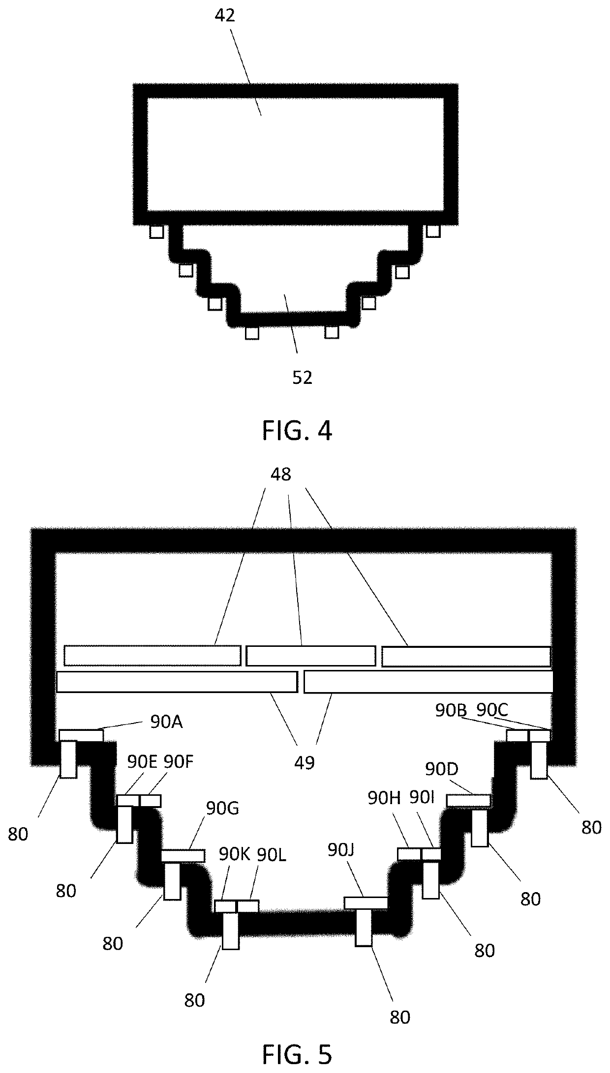
[0033]The present disclosure relates to a battery electric vehicle supermodule shaped, sized, dimensioned, and designed for placement within a vehicle. The vehicle may be an electric or hybrid-electric vehicle. The supermodule may be designed such that the supermodule is an electrical power distribution module for providing power to various vehicle components. The electrical power distribution module may be designed in such a way that it is connected to an energy storage device, such as one or more battery packs. The electrical power distribution module may provide a housing for key functional circuit boards of the vehicle. The electrical power distribution module may provide electrical power having different voltages to the various vehicle components. The electrical power distribution module may reduce the required space for mounting. The electrical power distribution module may reduce or simplify the routing of media between vehicular components. This may allow for simplified asse...


PUM

PropertyMeasurementUnit
voltageaaaaaaaaaa
voltageaaaaaaaaaa
voltageaaaaaaaaaa

Abstract

An electrical power distribution module for a vehicle. The electrical power distribution module provided with an upper module and a lower module. The upper module provided with circuit boards for various vehicle components and a temperature control system. The lower module provided with a plurality of isolated busbars, isolated from the surrounding structure. Each isolated busbar is one of a positive busbar, a negative busbar, and a ground busbar. The plurality of isolated busbars are arranged on opposite sides of the lower module and are arranged in an alternating fashion based on polarity. The plurality of isolated busbars are electrically connected to the circuit boards. The plurality of electrical connectors are spaced apart from each other and are configured to provide power and ground connections for the vehicle components. The plurality of isolated busbars are configured to carry different voltages.

Description

TECHNICAL FIELD[0001]Embodiments of the present disclosure relate generally to a supermodule for a battery electric vehicle, and more particularly, a supermodule for cable connections between components for a battery electric vehicle.BACKGROUND[0002]Currently, vehicles, such as electric and hybrid-electric vehicles, require a lot of components to operate the vehicle. With the large number of components on a battery electric vehicle (BEV), there is congestion of power, ground, and signal cables, as well as coolant pipes, which makes the area around all of the electrical components very difficult to connect all the media as well as work on them when service is required.SUMMARY[0003]According to an embodiment, an electrical power distribution module for a vehicle may include an upper module, the upper module may include at least one circuit board configured for mounting in the upper module; and a temperature control system, the temperature control system configured to control a tempera...

Claims


Application Information

Patent Timeline
Patent Type & Authority Applications(United States)
IPC IPC(8): H01M2/10B60R16/033B60R16/04H01M2/22H02G5/06B60L50/60
CPCH01M2/1083B60R16/033B60L50/66H01M2/22H02G5/06B60R16/04B60R16/02H01M50/507H01M50/509H01R25/14H01R2201/26B60L2240/525B60L1/02B60L2200/36Y02E60/10Y02T10/70B60L50/50B60L58/32H02B1/56H02G3/03H02G5/10
Inventor BURCHETT, CHAD
Owner VOLVO LASTVAGNAR AB
Features
  • Generate Ideas
  • Intellectual Property
  • Life Sciences
  • Materials
  • Tech Scout
  • Unparalleled Data Quality
  • Higher Quality Content
  • 60% Fewer Hallucinations
Learn More