Developing apparatus and image forming apparatus

a technology of developing apparatus and image forming apparatus, which is applied in the direction of electrographic process apparatus, instruments, optics, etc., can solve the problems of inability to accurately detect the change in the developer surface, limited position for installing magnetic sensors, etc., and achieve the effect of accurate ascertaining and increasing the amount of developer in the developer tank

Active Publication Date: 2022-02-24
SHARP KK
View PDF0 Cites 0 Cited by
  • Summary
  • Abstract
  • Description
  • Claims
  • Application Information

AI Technical Summary

Benefits of technology

[0017]According to one aspect of the present disclosure, by providing a developer detection sensor at a point where the variation is large, it is possible to accurately ascertain that the developer tank has become full when the amount of developer in the developer tank increases. Furthermore, by carefully observing the developer to be discharged during driving, it is possible to accurately ascertain that the developer tank has become full.

Problems solved by technology

In the above-described developing apparatus, however, the structure of the developing container and the operation of each part cause the developer to be unevenly distributed, and therefore, depending on the position where the detection means is provided, the change in the developer surface may not be correctly detected.
In the above-described developing apparatus, it is necessary to install a magnetic sensor at a position for detecting a developer in a storage chamber, and there is a problem that the position for installing the magnetic sensor is limited.

Method used


Image

  • Developing apparatus and image forming apparatus
  • Developing apparatus and image forming apparatus
  • Developing apparatus and image forming apparatus

Examples


first embodiment

[0027]Hereinafter, an image forming apparatus according to a first embodiment of the present disclosure will be described with reference to the drawings.

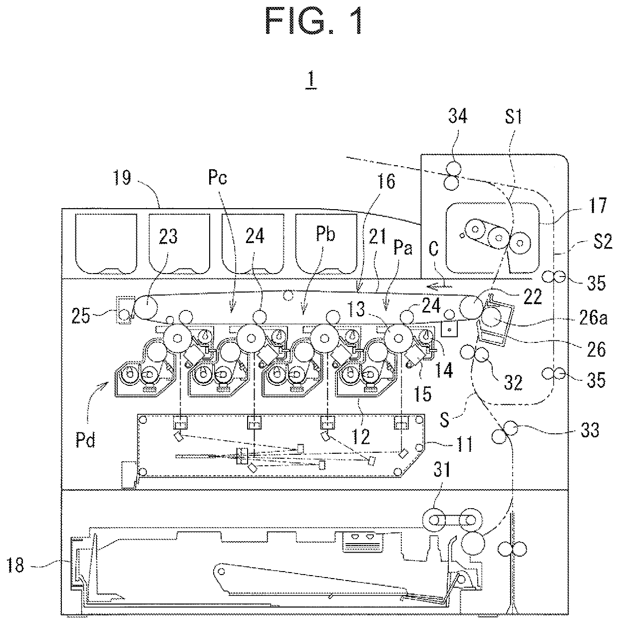
[0028]FIG. 1 is a schematic side view of the image forming apparatus according to the first embodiment of the present disclosure.

[0029]An image forming apparatus 1 according to the first embodiment of the present disclosure includes an exposure device 11, a developing apparatus 12, a photosensitive drum 13, a cleaner device 14, a charger 15, an intermediate transfer belt device 16, a fixing device 17, a paper feed tray 18, a paper output tray 19, and a paper conveyance path S, and forms a multicolor image or a monochromatic image on a predetermined paper sheet in response to image data transmitted from outside.

[0030]The image data handled by the image forming apparatus 1 is according to a color image using black (K), cyan (C), magenta (M), and yellow (Y) colors. Four sets of the developing apparatus 12, the photosensitive drum 13, t...

second embodiment

[0070]Next, an image forming apparatus (developing apparatus) according to a second embodiment of the present disclosure will be described with reference to the drawings. Since the structure of the image forming apparatus according to the second embodiment is generally the same as that of the first embodiment, similar reference numerals are used and further description thereon is not given.

[0071]FIG. 7 is a schematic side view near the discharge guide of the developing apparatus according to the second embodiment of the present disclosure. In FIG. 7, the vicinity of the end of the developing apparatus 12 where the discharge guide 51 is provided is extracted and illustrated schematically, and other portions of the developer tank 50 and a portion supported by the image forming apparatus 1 are omitted.

[0072]The developing apparatus 12 has an enclosure 110 to which the developer tank 50 is mounted, and the developer tank 50 is removable from the enclosure 110. The enclosure 110 has an e...

third embodiment

[0074]Next, an image forming apparatus (developing apparatus) according to a third embodiment of the present disclosure will be described with reference to the drawings. Since the structure of the image forming apparatus for the third embodiment is essentially equivalent to that of the first and second embodiments, similar reference numerals are used, and its description and drawing are omitted.

[0075]FIG. 8 is a schematic cross-sectional view of a discharge guide near the developing apparatus according to a third embodiment of the present disclosure.

[0076]The third embodiment differs from the first embodiment in the position at which the developer detection sensor GS is provided. Specifically, in the third embodiment, the developer detection sensor GS (a third sensor 103) is provided in the discharge guide and detects the amount of the developer discharged from the discharge port 52 according to the amount of the developer in the discharge guide51. In other words, since the amount o...


PUM


Abstract

A developing apparatus includes: a developer tank that contains a developer; and conveyance members that convey the developer while agitating the developer. The conveyance members include a first screw and a second screw. The developer tank includes: a first storage chamber in which the first screw is provided; a second storage chamber in which the second screw is provided; a partition that separates the first storage chamber from the second storage chamber; and a flow area that opens the partition to flow the developer between the first storage chamber and the second storage chamber; a developer detection sensor that detects an amount of the developer thereof; a discharge port that discharges the developer; and a discharge guide that guides the developer to the discharge port. The developer detection sensor detects that the developer tank is full according to the amount of the developer.

Description

CROSS-REFERENCE TO RELATED APPLICATION[0001]The present application claims priority from Japanese Patent Application Number 2020-140186, the content to which is hereby incorporated by reference into this application.BACKGROUND OF THE INVENTION1. Field of the Invention[0002]One aspect of the present disclosure relates to a developing apparatus and an image forming apparatus, which include a developer tank.2. Description of the Background Art[0003]Conventionally, there has been known an electrophotographic image forming apparatus, and in such an image forming apparatus, a developing apparatus having a developer tank containing therein a developer is applied. The developing apparatus supplies a developer used for image formation, but inclination of the developer tank, etc., may cause uneven distribution of the developer within the developer tank. Therefore, a method for stabilizing the developer surface within the developer tank at an appropriate position has been proposed (see, for ex...

Claims


Application Information

Patent Timeline
Patent Type & Authority Applications(United States)
IPC IPC(8): G03G15/08
CPCG03G15/0891G03G15/0858G03G15/0889G03G15/0893G03G15/086
Inventor SUDOH, TERUYOSHI
Owner SHARP KK
Why Eureka
Try Eureka