Vibration damping device

Active Publication Date: 2022-03-03
TOKAI RUBBER IND LTD +1
View PDF2 Cites 0 Cited by
  • Summary
  • Abstract
  • Description
  • Claims
  • Application Information

AI Technical Summary

Benefits of technology

The patent text describes a vibration damping device that prevents movement of the attachment member in a lateral-insertion type. This is important because a dislodged attachment member can cause problems. The device uses a hook part on the attachment member that fits into a locking hole on the bracket to prevent movement. The technical effect of this invention is better stability and reliability of the attachment system.

Problems solved by technology

If the input is unexpectedly large, resistance to dislodgement cannot be sufficiently exerted, and there is a risk that the hook part and the locking hole may be unlocked.

Method used


Image

  • Vibration damping device
  • Vibration damping device
  • Vibration damping device

Examples


Embodiment Construction

[0040]Practical embodiments of the present invention will be described below in reference to the drawings.

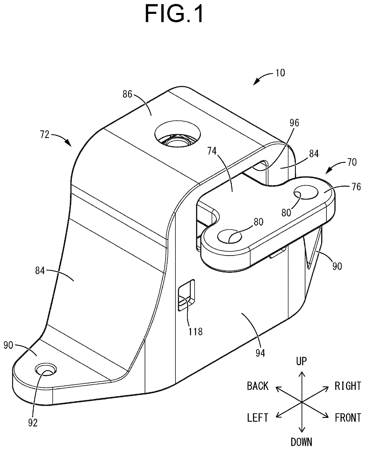
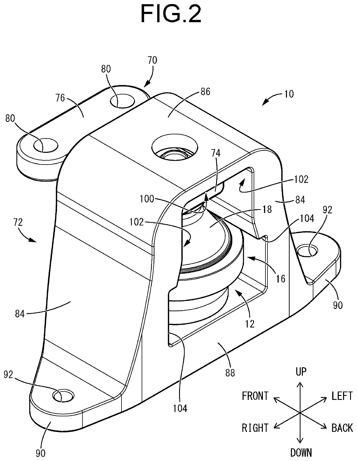
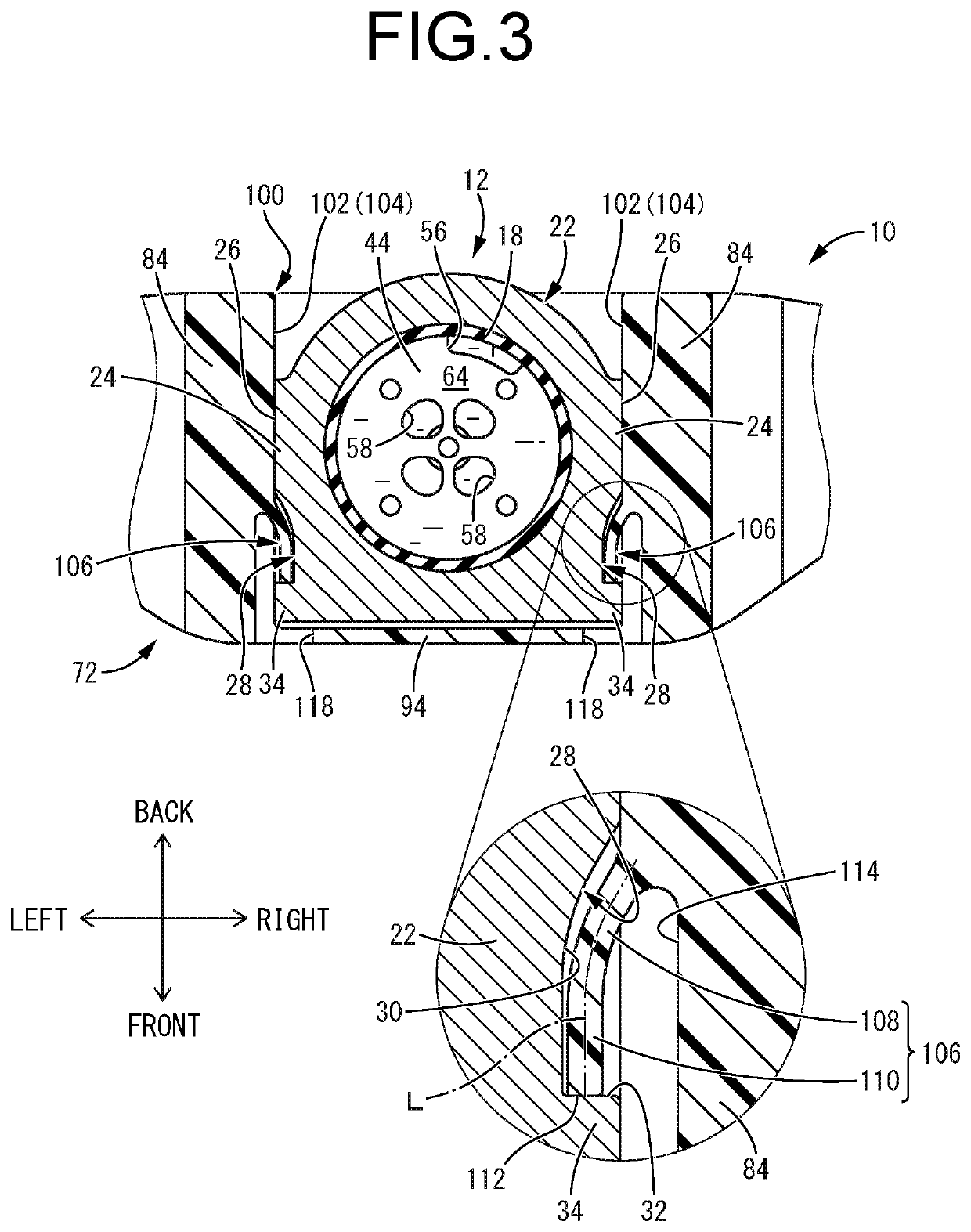
[0041]Referring first to FIGS. 1 to 5, there is depicted an automotive engine mount 10 as a first practical embodiment of a vibration damping device according to the present invention. The engine mount 10 includes a mount main unit 12 serving as a vibration-damping device main unit. As shown in FIGS. 4 to 6, the mount main unit 12 has a structure in which a first attachment member 14 and a second attachment member 16 are connected by a main rubber elastic body 18. In the following description, as a general rule, the vertical direction refers to the vertical direction in FIG. 4, which coincides with the mount center axis direction, and the left-right direction refers to the left-right direction in FIG. 3, which coincides with the width direction of an outer bracket 72 to be described later. Besides, as a general rule, the front-back direction refers to the vertical direction in F...


PUM

PropertyMeasurementUnit
Flexibilityaaaaaaaaaa
Widthaaaaaaaaaa
Deformation enthalpyaaaaaaaaaa

Abstract

A vibration damping device including a vibration-damping device main unit attached to a bracket from a lateral side by a second attachment member being fitted to opposed walls provided on widthwise opposite sides of the bracket. The bracket includes flexible latches extending from the respective opposed walls forward in a direction of attachment. The second attachment member includes outer recesses respectively opening onto surfaces overlapped with the respective opposed walls. Each latch has a slope portion sloping inward in a width direction of the bracket such that a distal end face of the latch is inserted in the corresponding outer recess. The distal end face of the latch is latched by a forward wall inner face of the outer recess, and displacement of the second attachment member relative to the bracket in a direction of dislodgment opposite to the direction of attachment is limited.

Description

INCORPORATED BY REFERENCE[0001]The disclosure of Japanese Patent Application No. 2020-144352 filed on Aug. 28, 2020 including the specification, drawings and abstract is incorporated herein by reference in its entirety.BACKGROUND OF THE INVENTION1. Field of the Invention[0002]The present invention relates to a vibration damping device for use in, for example, an automotive engine mount or the like.2. Description of the Related Art[0003]Conventionally, a vibration damping device in which a first attachment member and a second attachment member are connected by a main rubber elastic body is used, for example, in an engine mount for a vehicle. As shown in U.S. Publication No. US 2020 / 0217391, the vibration damping device is such that a second attachment member is attached to the vehicle via a bracket. The second attachment member and the bracket are assembled by fitting parts provided on widthwise opposite sides of the second attachment member being respectively fitted from the lateral...

Claims


Application Information

Patent Timeline
IPC IPC(8): F16F13/08B60K5/12F16F13/10
CPCF16F13/085F16F2224/025F16F13/108B60K5/1208B60K5/1275F16F15/08F16F13/103F16F2226/041B60K5/1216
Inventor TANAKA, SHINGOANDO, RYUICHIOKI, KENJIARAI, YUSUKEKAWABE, KEISUKE
Owner TOKAI RUBBER IND LTD
Why Eureka
Try Eureka