Gas strut, method for producing the gas strut, drive for a flap with the gas strut

a gas strut and gas strut technology, applied in the direction of spring/damper functional characteristics, shock absorption devices, mechanical devices, etc., can solve the problems of unsatisfactory high power consumption of the motor, unfavourable spring rate, and high cost of producing spring struts of sufficient dimensions

Active Publication Date: 2022-03-10
STABILUS
View PDF8 Cites 0 Cited by
  • Summary
  • Abstract
  • Description
  • Claims
  • Application Information

AI Technical Summary

Problems solved by technology

A high motor power requires an undesirably large and heavy motor and results in an undesirably high power consumption of the motor.
Option b has the disadvantage that spring struts of sufficient dimensions are very expensive to produce and heavy and have an unfavourable spring rate.
Furthermore, the temperature dependence cannot be completely overcome.
Option c is technically very complex and above all cannot be implemented economically with regard to assembly.
Furthermore, very high pressure may occur in the equalizing space under certain operating conditions, which places a great stress on sealing elements and tubes of the gas strut.
Furthermore, the overall length of the gas strut is lengthened by the temperature compensation being achieved by a lengthening of the working space, which is considerable compared with an uncompensated gas strut, which clearly restricts the possible applications.
As a result, the restoring space can be made of sufficiently large dimensions so that the pressure of the restoring medium during operation of the gas strut is limited to values which are non-critical for conventional sealing means or seal and materials of the equalizing cylinder and of the working cylinder, for example below 250 bar.
In particular, a sufficiently large restoring space ensures that the pressure of the restoring medium remains limited to values which are non-critical for conventional sealing means or seal and materials of the equalizing cylinder and of the working cylinder, for example below 250 bar.
Since the spring force in conventional gas struts increases with increasing temperature, this leads to a very large force having to be applied by the electromechanical drive or an operator at high temperatures in order to close the flap.
Therefore, the drive system has to comprise a very powerful electromechanical drive, which is expensive, takes up a lot of installation space and uses a lot of energy during operation.
Furthermore, a large amount of wear of the electromechanical drive and other parts mechanically connected to the flap, for example hinges, occurs.
Although a spring strut has a virtually temperature-independent spring force, it is larger, heavier and more expensive than a gas strut of comparable spring force.

Method used


Image

  • Gas strut, method for producing the gas strut, drive for a flap with the gas strut
  • Gas strut, method for producing the gas strut, drive for a flap with the gas strut

Examples


Embodiment Construction

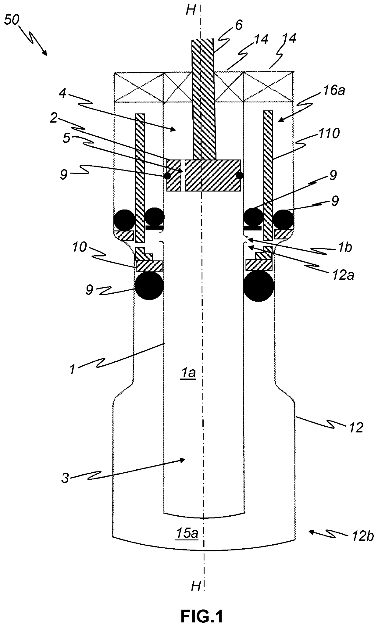
[0067]FIG. 1 shows a schematic longitudinal section through a gas strut 50 according to embodiments of the invention along its stroke axis H.

[0068]The gas strut 50 comprises a working cylinder 1 which encloses an inner working space 1a filled with a working gas, not illustrated, e.g., nitrogen. The working cylinder 1 is for example formed substantially hollow-cylindrically and arranged coaxially to the stroke axis H. The working cylinder 1 has for example a length along the stroke axis H of 230 mm and transversely to the stroke axis an internal diameter of 16 mm and an external diameter of 19 mm.

[0069]The gas strut 50 comprises a working piston 2 mounted displaceably along a stroke axis H in the inner working space 1a. The working piston 2 is for example formed substantially cylindrically and arranged coaxially to the stroke axis H.

[0070]The working piston 2 subdivides the interior 1a of the working cylinder 1 into a first working chamber 3 and a second working chamber 4, which lie ...


PUM


Abstract

Provided is a gas strut, including: an outer working space arranged radially to the stroke axis between the working cylinder and the equalizing cylinder, the outer working space being connected to the inner working space in a gas-conducting manner; an equalizing piston enclosing the working cylinder radially to the stroke axis, the equalizing piston) being mounted displaceably along the stroke axis, delimiting the outer working space on one side transversely to the stroke axis and being subjected to a pressure of the working medium and a pressure of the equalizing medium so as to increase the volume of the outer working space; and a restoring medium arranged in a restoring space radially to the stroke axis between the working cylinder and the equalizing cylinder, the equalizing piston being subjected to a pressure of the restoring medium so as to decrease the volume of the outer working space.

Description

CROSS-REFERENCE TO RELATED APPLICATIONS[0001]This application claims priority to DE 10 2020 123 636.0, having a filing date of Sep. 10, 2020, the entire contents of which are hereby incorporated by reference.FIELD OF TECHNOLOGY[0002]The following relates to a gas strut with a working cylinder which encloses an inner working space filled with a working gas, a working piston mounted displaceably along a stroke axis in the inner working space, an equalizing cylinder which encloses the working cylinder at least over a partial length of the working cylinder along the stroke axis, and an equalizing medium which expands upon an increase in temperature, arranged in an equalizing space radially to the stroke axis between the working cylinder and the equalizing cylinder.[0003]The following furthermore relates to a method for producing the gas strut and to a drive for a flap with the gas strut.BACKGROUND[0004]The gas contained in gas struts expands as the temperature T rises and contracts as t...

Claims


Application Information

Patent Timeline
Patent Type & Authority Applications(United States)
IPC IPC(8): F16F9/52F16F9/06F16F9/43
CPCF16F9/52F16F9/064F16F9/43F16F9/062F16F9/0209F16F9/526B64C13/36F16F2230/0011F16F2222/02F16F9/0227F16F2228/002
Inventor REISER, ALEXANDERPROBST, ULRICHBEIB, FELIX
Owner STABILUS
Why Eureka
Try Eureka