
Switch assembly and power tool

Pending Publication Date: 2022-03-24
GLOBE (JIANGSU) CO LTD
View PDF13 Cites 0 Cited by
  • Summary
  • Abstract
  • Description
  • Claims
  • Application Information

AI Technical Summary

Benefits of technology

The present invention is a switch assembly that has a start switch and a locking switch positioned in opposite positions. The start switch is connected to the housing with a pivot, and the locking switch is connected to the housing and can move between a locked position and a releasing position. The locking switch is in contact with the start switch when in the locked position, and disengages from the start switch when in the releasing position. This switch assembly is convenient to use and is designed to prevent accidental starting of the engine.

Problems solved by technology

When user just holds but does not use the power tool, the start switch would be pressed unintentionally to start the power tool by mistake, that will cause some dangerous situations.
However, when using the grip type switch assembly mentioned above, there is a defect that it is difficult to significantly distinguish between the action of starting the safety switch and the action of actuating the start switch.
Thereby the start switch would be actuated by mistake so that dangerous situation occurs.
Under new safety usage regulations of the tools, potentially unsafe factors of the grip type switch assembly limit the further application of the tool.

Method used


Image

  • Switch assembly and power tool
  • Switch assembly and power tool
  • Switch assembly and power tool

Examples


Embodiment Construction

[0033]In order to make the objectives, technical solutions, and advantages of the disclosure clearer, the drawings combined with embodiments will be described below in detail.

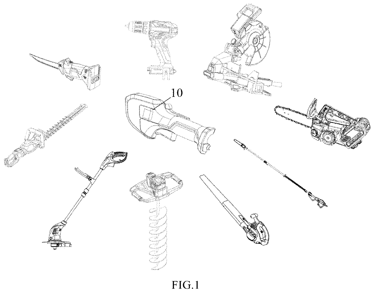
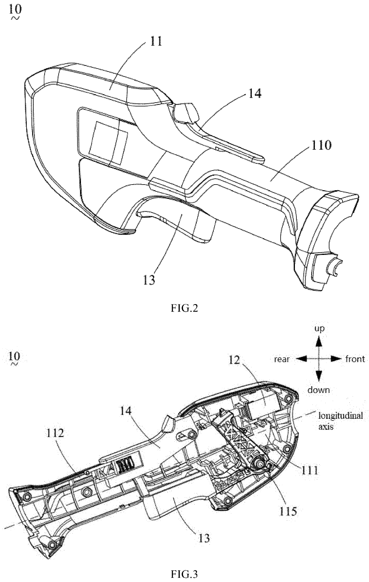
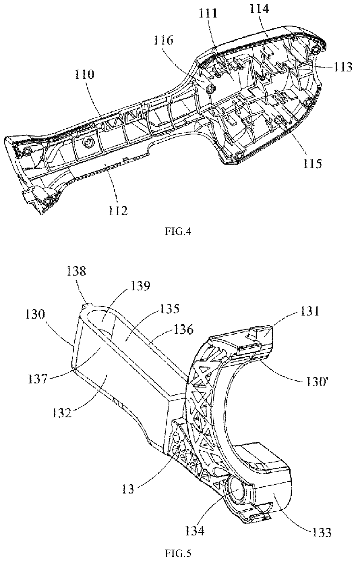
[0034]As shown in FIG. 1, the disclosure provides a power tool which may be a hedge trimmer, an electric saw, a blower, a chain saw or a string trimmer, or other type of hand-held power tool. All of which can be operated by the switch assembly 10 of the disclosure, not limited herein. These power tools may typically include a work assembly, a drive assembly, a battery assembly, and a switch assembly 10 for implementing the functions of the power tool, such as mowing, blowing and the like. The drive assembly may be connected with the work assembly to drive the work assembly to move. The drive assembly may typically be a motor. The battery assembly may supply power for the drive assembly. The switch assembly 10 may be used for starting or closing the power tool (including the drive assembly and the battery assemb...


PUM


Abstract

The disclosure provides a switch assembly and a power tool. The switch assembly includes a housing which extends along the longitudinal axis, a main control switch which is housed within the housing, a locking switch which is slidably connected with the housing and can move between a locking position and a releasing position, and a start switch which is rotably connected with the housing by a pivot. The locking switch is in contact with the start switch when the locking switch is in the locking position, and the start switch is in a locked state. The locking switch is disengaged from the start switch when the locking switch is in the releasing position, and the start switch is in a released state.

Description

CROSS REFERENCE TO RELATED APPLICATION[0001]The present application is based on, and claims the priority from, Chinese application number CN202011006740.8, filed on Sep. 23, 2020, the disclosure of which is hereby incorporated by reference herein in its entirety for all purposes.TECHNICAL FIELD[0002]The disclosure relates to a switch assembly and power tool which belongs to the technical field of garden tools.BACKGROUND[0003]At present, the power tool is usually provided with a handle for user to hold, on which a start switch is disposed. When user just holds but does not use the power tool, the start switch would be pressed unintentionally to start the power tool by mistake, that will cause some dangerous situations. So a safety switch is needed to be arranged on the power tool to prevent the switch assembly from accidentally starting when the user does not need the power tool to work.[0004]A conventional start switch is typically disposed on the lower side of the handle and faces ...

Claims


Application Information

Patent Timeline
IPC IPC(8): H01H21/22H01H21/04B25F5/02
CPCH01H21/22B25F5/02H01H21/04H01H9/20H01H3/20B25F3/00
Inventor WANG, DOUSHI
Owner GLOBE (JIANGSU) CO LTD
Learn More