Conical refrigerant coil

a coil and refrigerant technology, applied in indirect heat exchangers, lighting and heating apparatus, heating types, etc., can solve the problems of reduced system efficiency, increased power consumption and strain on compressors, and common failure points of solder joints, etc., to reduce or eliminate air flow

Active Publication Date: 2022-04-07
GREEN AIR INC
View PDF5 Cites 1 Cited by
  • Summary
  • Abstract
  • Description
  • Claims
  • Application Information

AI Technical Summary

Benefits of technology

[0011]The air handler may further comprise a plug positioned at a narrow end of the conical refrigerant coil to reduce or eliminate air flow through the narrow end of the conical refrigerant coil.

Problems solved by technology

Such a shape causes turbulence in the air flowing through the air handler, which reduces the efficiency of the system.
Such solder joints are common failure points.
Additionally, the zig-zag path of the refrigerant due to the many dozens or even hundreds of U-turns in the coil increases the backpressure, resulting in increased power consumption and strain on the compressor which will likely shorten the life of the compressor.

Method used


Image

  • Conical refrigerant coil
  • Conical refrigerant coil
  • Conical refrigerant coil

Examples


Embodiment Construction

[0036]Certain terminology is used in the following description for convenience only and is not limiting. The words “lower,”“bottom,”“upper,” and “top” designate directions in the drawings to which reference is made. The words “inwardly,”“outwardly,”“upwardly” and “downwardly” refer to directions toward and away from, respectively, the geometric center of the device, and designated parts thereof, in accordance with the present disclosure. Unless specifically set forth herein, the terms “a,”“an” and “the” are not limited to one element, but instead should be read as meaning “at least one.” The terminology includes the words noted above, derivatives thereof and words of similar import.

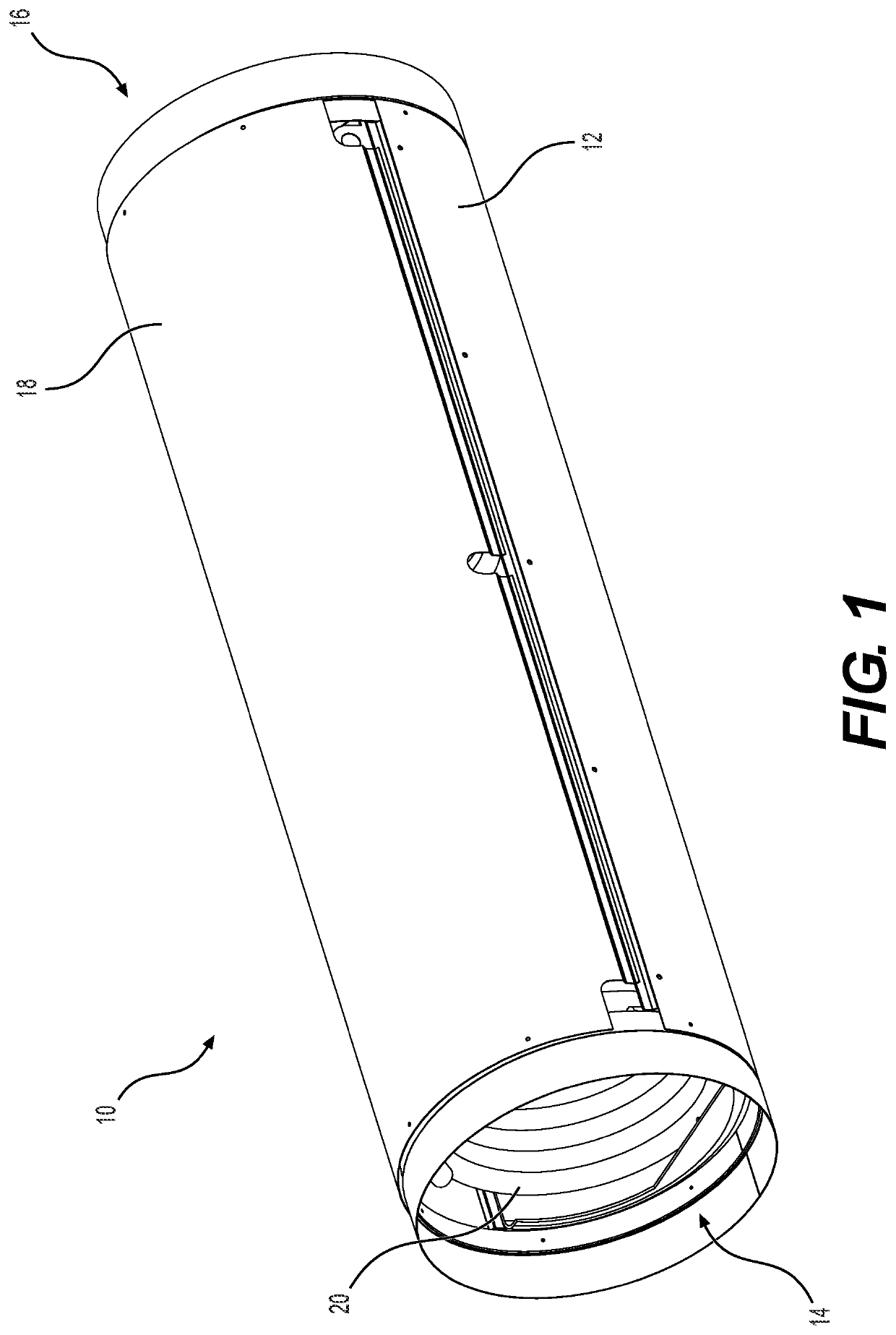
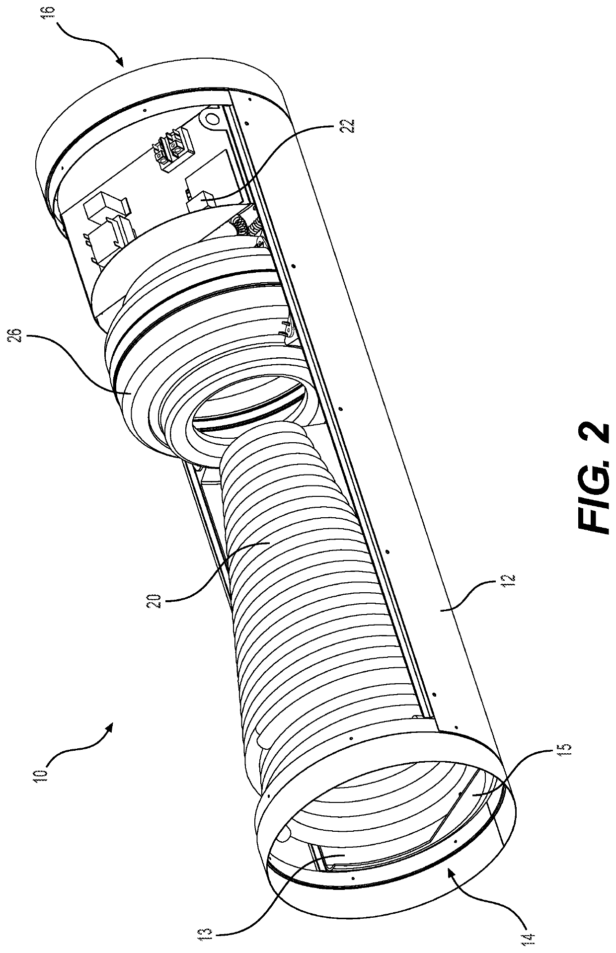
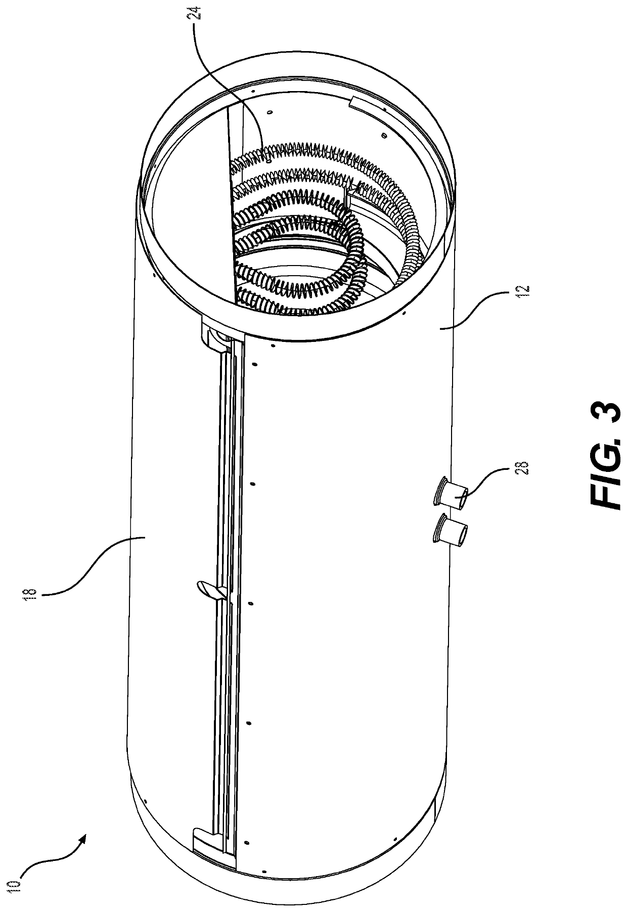
[0037]Embodiments of the invention are directed to a cylindrical air handler and a conical refrigerant coil for use in such a cylindrical air handler. Such a cylindrical air handler reduces turbulence of the air flowing through the air handler, and therefore has increased efficiency. The conical refrigera...


PUM


Abstract

A conical refrigerant coil comprises a plurality of pipes, each pipe arranged in a conical spiral and each pipe comprising a plurality of loops. At least some of the loops of each pipe of the plurality of pipes are arranged alternatingly along at least a portion of a length of the coil.

Description

CROSS-REFERENCE TO RELATED APPLICATIONS[0001]This application claims priority to pending U.S. Provisional Application Ser. No. 63 / 086,806, filed Oct. 2, 2020, the contents of which are incorporated herein by reference in its entirety.FIELD OF THE INVENTION[0002]The present technology relates generally to heating, ventilation, and air conditioning (HVAC) system.BACKGROUND[0003]Heating, ventilation, and air conditioning (HVAC) systems heat and / or cool air within a house or other enclosed space by drawing air through return ducts into an air handler where the air is heated or cooled and then forced back into the space through supply ducts. The air handler typically includes a refrigerant coil through which a refrigerant is pumped. Air flowing across the refrigerant coil cools the air. The air handler also typically includes one or more heating elements, which may be one or more resistive wire coils in an electric system or one or more burners in a gas or oil system. Air flowing across ...

Claims


Application Information

Patent Timeline
Patent Type & Authority Applications(United States)
IPC IPC(8): F25B39/04
CPCF25B39/04F25B39/028F28D1/024F28D1/0472F28D7/028F28D2021/0071F28F1/122F28F1/124F28F1/36F28F9/0275F24F1/0067F24F13/30
Inventor ROADY, NATHANIEL S.SACHDEVA, EVAN PAUL
Owner GREEN AIR INC
Why Eureka
Try Eureka