Flow diverter and basket

a flow diverter and basket technology, applied in the direction of cleaning using liquids, washing/rinsing machines for tableware, household cleaners, etc., can solve the problems of difficult to obtain flow through each jet, affecting the overall efficiency and performance of the machine, and not always optimizing the volume within the tank, so as to improve the flow consistency

Active Publication Date: 2022-05-10
UNIFIED BRANDS
View PDF24 Cites 0 Cited by
  • Summary
  • Abstract
  • Description
  • Claims
  • Application Information

AI Technical Summary

Benefits of technology

[0008]The present invention comprises a system for and a method of diverting flow within a multi-jet manifold of a fluid circulating system (such as a continuous motion fluid washing or thawing machine) so as to reduce or eliminate flow inconsistencies and / or to otherwise enhance evenness of jet flows through a plurality of nozzles, apertures, or the like. The system includes a discharge manifold defining a primary flow path and a plurality of outlets (each being a “nozzle”) defining respective secondary flow paths. In some embodiments, each nozzle defines an inlet positioned within the primary flow path and / or adjacent to the primary flow path, such as in a void associated with flow diverters of the present invention. By positioning nozzle inlets within a void positioned adjacent to the primary flow path, hydraulic skip is reduced when compared with nozzle inlets positioned within the primary flow path. In this way, fluid flow into such nozzles (and therefore out of such nozzles) is more consistent.
[0009]While each nozzle includes an inlet, not all nozzle inlets are required to be positioned within a void for the invention to provide benefits over the prior art. Instead, because hydraulic skip is generally most severe at the first nozzle along the primary flow path and diminishes for each subsequent nozzle, benefits can be gained by creating voids associated with a first nozzle and / or a first set of nozzles along the primary flow path. In some embodiments, each void is created by positioning a first obtrusion member directly upstream of a respective nozzle and positioning a second obtrusion member directly downstream of such nozzle. Each obtrusion member extends into the interior volume of the discharge manifold from a rear wall / portion of the discharge manifold, thereby creating the void and (at least locally) reducing the width of the primary flow path. The respective nozzle extends through the primary flow path from a front wall / portion of the discharge manifold, thereby creating a secondary flow path that effectively extends through the primary flow path.
[0010]The present invention also comprises a rack assembly that is configured to hold a plurality of full and half pans during a fluid flow cycle. A rigid member of the rack assembly defines an interior volume for holding a plurality of other items, thereby maximizing space within the tank. The rack assembly is configured to be removable, thereby increasing versatility of the tank. The rack assembly is configured to increase efficiency and / or productivity prior to a fluid flow cycle, such as by assisting users determine where to position sheet pans (or other items) within the tank. The rack assembly is configured to increase efficiency of a fluid flow cycle, such as by reducing or eliminating movement of items and / or otherwise decreasing adverse effects associated with the same (i.e. impacts, pinning, etc.). The rack assembly is configured to increase efficiency and / or productivity after a fluid flow cycle, such as by assisting users determine whether sheet pans (or other items) are currently positioned within the tank and / or where within the tank such items are positioned.

Problems solved by technology

Although the prior art pot and pan washing machine disclosed in U.S. Pat. No. 4,773,436 provides an exceptional wash / fluid action, many of the components discussed above hinder the overall efficiency and performance of the machine.
Nevertheless, prior to the advent of the instant invention, even flow through each jet has been difficult to obtain, often creating inconsistent flow within the wash / fluid tank.
Unfortunately, such features do not always optimize the volume within the tank.
Although many of the systems of the prior art provide superior wash, defrost, deglaze, and other fluid flow actions, it is often difficult for users of such systems determine whether an additional item can be placed in a tank and / or whether all items have been removed from the tank.
This is particularly difficult to determine when fluid within the tank is murky and / or when the user's view is otherwise obstructed, such as by suds on the surface of the water, by other items within the water, or the like.

Method used


Image

  • Flow diverter and basket
  • Flow diverter and basket
  • Flow diverter and basket

Examples


Embodiment Construction

[0040]As required, a detailed embodiment of the present invention is disclosed herein; however, it is to be understood that the disclosed embodiment is merely exemplary of the principles of the invention, which may be embodied in various forms. Therefore, specific structural and functional details disclosed herein are not to be interpreted as limiting, but merely as a basis for the claims and as a representative basis for teaching one skilled in the art to variously employ the present invention in virtually any appropriately detailed structure.

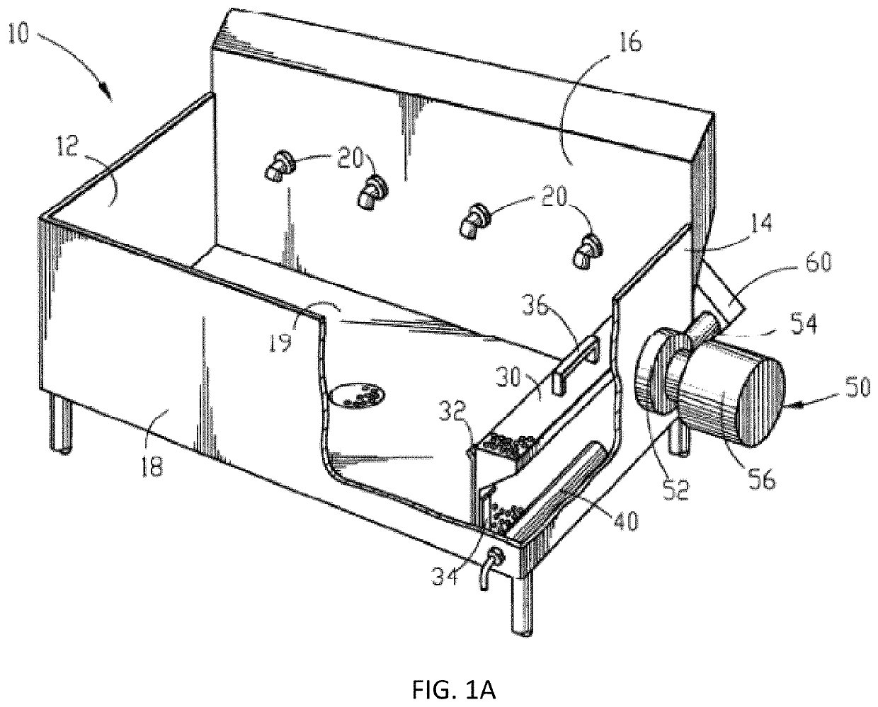
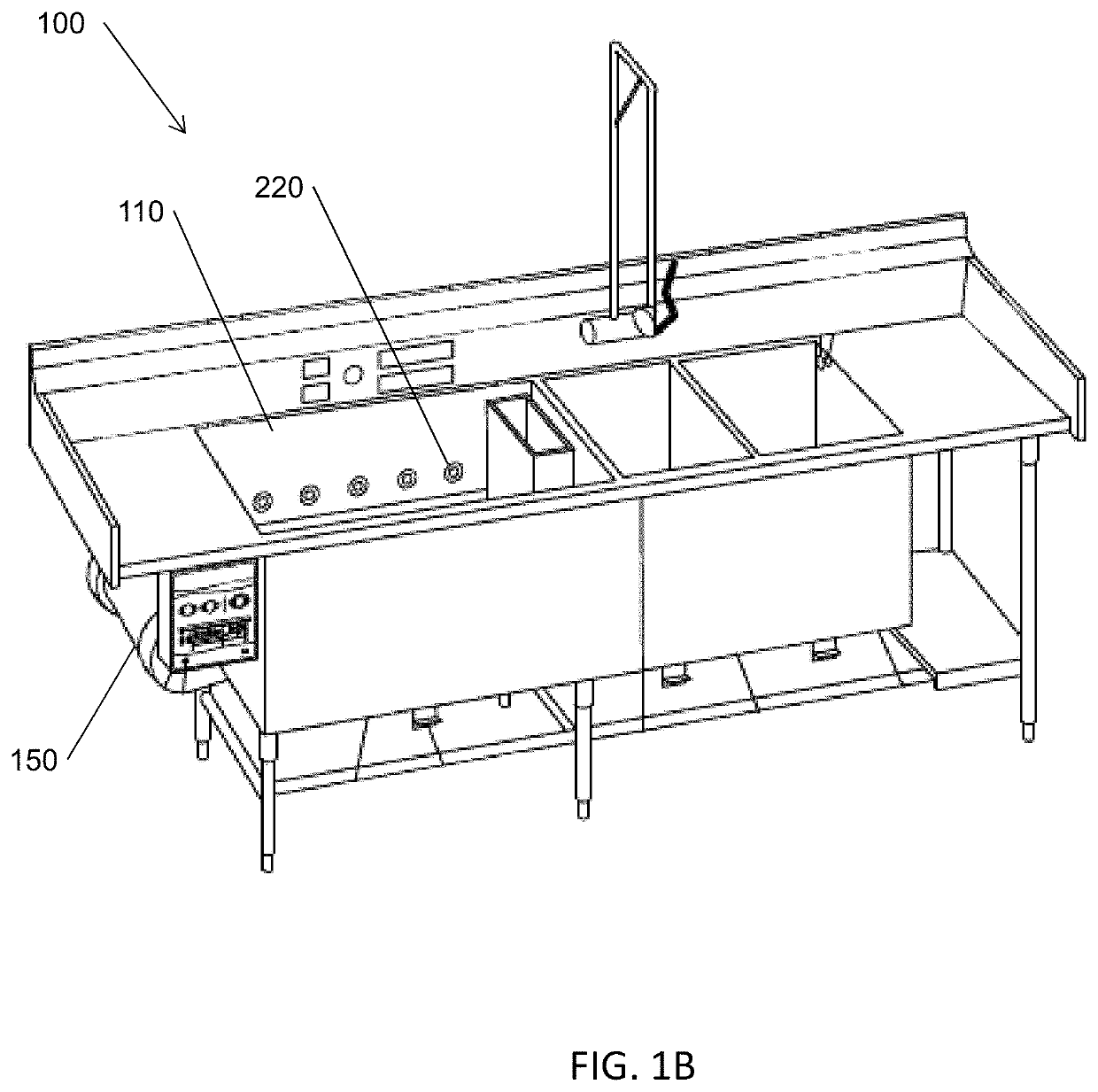
[0041]Referring to FIG. 1B, some machines 100 of the present invention include a tank 110 defining an interior volume 115 for holding a volume of fluid (for washing, thawing, deglazing or other purposes—broadly referred to herein as “washing” or “soaking”) and a pump 150 for directing fluid through a plurality of nozzles 220 into the tank, thereby creating a rolling action within the tank 110. In some embodiments, the pump 150 draws fluid from...


PUM


Abstract

A system for and method of improving fluid flow is provided. The system includes a discharge manifold defining a primary flow path partially obstructed by one or more flow diverter. The flow diverter includes an obtrusion pair, each obtrusion of the obtrusion pair extending from a rear wall of the discharge manifold into an interior area of the discharge manifold, thereby creating a void along the primary flow path. The system further includes a first nozzle extending through the primary flow path and into the void such that a nozzle inlet of the first nozzle is positioned at least partially within the void. The system further includes a plurality of subsequent nozzles, each of the first and subsequent nozzles defining a respective secondary flow path for directing fluid away from the discharge manifold. The method includes utilizing obtrusion pairs to reduce or eliminate hydraulic skip.

Description

CROSS-REFERENCE TO RELATED APPLICATIONS[0001]This application claims priority pursuant to 35 U.S.C. 119(e) to U.S. Provisional Patent Application Ser. No. 62 / 742,778, filed Oct. 8, 2018, the entire disclosure of which is incorporated herein by reference. This application is a continuation-in-part application of co-pending of U.S. Design patent application No. 29 / 678,355, filed on Jan. 28, 2019, the entire disclosure of which is incorporated herein by reference.FIELD OF THE INVENTION[0002]The present invention relates generally to a fluid circulating system, such as a continuous motion washing / soaking machine, components of a fluid circulating system, and methods of use of a fluid circulating system, including the washing of wares, food, or other items, thawing of food items, and the like. More specifically, the present invention is concerned with flow diverters for a continuous motion machine (such as a continuous motion washing or thawing machine) and a method of diverting flow for...

Claims


Application Information

Patent Timeline
Patent Type & Authority Patents(United States)
IPC IPC(8): A47L15/42B08B3/04B08B3/06B08B3/10
CPCB08B3/048A47L15/4214B08B3/06B08B3/10
Inventor LICATA, MICHAEL P.SINGHAL, ATULAGRAWAL, ABHISHEKSEISS, RICHARDMOORE, ROGERCHURCHILL, MARK
Owner UNIFIED BRANDS
Why Eureka
Try Eureka