Payload mounting method, system, and apparatus

a payload and mounting method technology, applied in the direction of cosmonautic components, cosmonautic parts, cosmonautic vehicles, etc., can solve the problems of serious flaws, general inapplicability, and inability to design a payload with an offset center of gravity, so as to reduce the transmission of moments

Pending Publication Date: 2022-04-21
REPRISE SPACE SOLUTIONS LLC
View PDF1 Cites 0 Cited by
  • Summary
  • Abstract
  • Description
  • Claims
  • Application Information

AI Technical Summary

Benefits of technology

[0010]This disclosure relates generally to a novel Evolved Expendable Launch Vehicle (EELV) Secondary Payload Adapter (ESPA) port small payload mounting system that permits maximum mass utilization of each ESPA port without regard to center of gravity constraints. In one or more embodiments, the apparatus and method include connecting, in the unused central volume of an ESPA ring, the adjacent faces of at least two payloads on opposing sides of an ESPA ring with a cross-reaching moment transmitting structure that reduces moments transmitted to the ESPA ring.
[0014]In all the embodiments, for the payloads to separate and deploy from the ESPA ring after arrival of the launch vehicle to the deployment destination, the payloads are attached to their respective ESPA ports by well-known separation systems. This is easily accomplished by utilizing any well-known separation system known in the prior art (e.g. a separation nut, pyrotechnic nut, Marmon clamp, etc.) that fastens the payload to the ESPA port.
[0017]In the second and third embodiments the larger diameter moment transmitting cylindrical structure generally should be sized such that the outer diameter of the moment transmitting cylindrical structure forms the base mounting diameter of the payloads. This provides the maximum bracing advantage to the payloads and contributes to efficient distribution of moments throughout the structure.
[0018]The main advantages of using the inventive mounting system is that it maximizes the mass utilization of each ESPA port without imposing the previously stated onerous center of gravity location constraints on the payloads.

Problems solved by technology

The ESPA ring has provided many more launch opportunities for smaller payloads since its introduction but it has a serious flaw.
In most cases, designing a payload with an offset center of gravity is not practical and as such, the center of gravity is generally located at approximately 50% of the radial length of the payload from the ESPA port plane.
This is generally not practical.
Thus, there is more available volume for satellites at a distance farther away from the ESPA port plane which, as stated earlier, tends to reduce the available launch mass capability due to the large moment arm imposed on the ESPA port by the payload.
Additionally, the volume on the inside diameter of an ESPA ring is generally unused since the payloads are mounted on the outer diameter faces of the ESPA ring.

Method used


Image

  • Payload mounting method, system, and apparatus
  • Payload mounting method, system, and apparatus
  • Payload mounting method, system, and apparatus

Examples


first embodiment

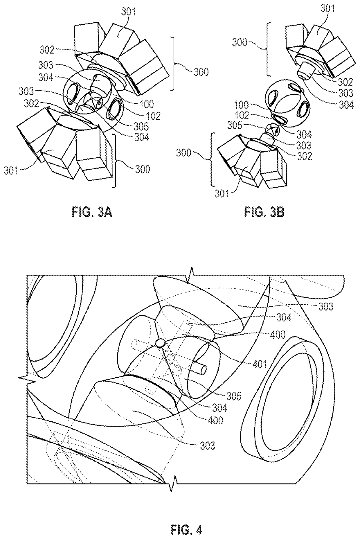
[0035]FIGS. 3A (pre-deployed configuration) and 3B (post deployed configuration) illustrate the inventive device showing the cross-reaching moment transmitting embodiment. Payload assembly 300 (or payloads) contains sub-payloads 301. Payload assemblies 300 mount on ESPA port attach structure 102 (attached to ESPA ring 100) utilizing bolts to attach well-known payload separation systems 302 (or a first payload separation system) that are in turn attached to payload assemblies 300 permitting payload assembly 300 separation when desired. Moment transmitting structure 303 is attached to payload assembly 300. An additional separation system (or second separation system, e.g. a separation nut and bolt) 304 attaches moment transmitting structure 303 to a central coupling device 305. The assemblies 303, 304 and 305, when fastened together, transmit loads and moments across the diameter of ESPA ring 100, thus relieving the moment loading on ESPA port attachment 102 and accomplishing the obje...

second embodiment

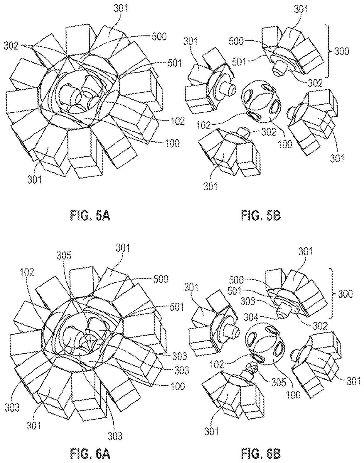
[0038]FIGS. 5A (pre-deployed configuration) and 5B (post deployed configuration) illustrate the inventive device showing the larger diameter moment transmitting cylindrical structure embodiment. Payload assembly 300 contains sub-payloads 301. Payload assemblies 300 mount on ESPA port attach structure 102 (attached to ESPA ring 100) utilizing bolts to attach well-known payload separation systems 302 that are in turn attached to payload assemblies 300 permitting payload assembly 300 separation when desired. Moment transmitting structure 500 is attached to payload assembly 300. An additional separation system (or a third separation system, e.g. a separation nut and bolt) 501 attaches moment transmitting structure 500 to adjacent payload assembly moment transmitting structure 500. The assemblies 500, when fastened together, transmit loads and moments to the other assemblies 500, thus relieving the moment loading on ESPA port attachments 102 and accomplishing the objective of reducing th...

third embodiment

[0040]FIGS. 6A (pre-deployed configuration) and 6B (post deployed configuration) illustrate the inventive device combining the cross-reaching moment transmitting embodiment with the larger diameter moment transmitting cylindrical structure embodiment. Payload assembly 300 contains sub-payloads 301. Payload assemblies 300 mount on ESPA port attach structure 102 (attached to ESPA ring 100) utilizing bolts to attach well-known payload separation systems 302 that are in turn attached to payload assemblies 300 permitting payload assembly 300 separation when desired. Moment transmitting structure 303 is attached to payload assembly 300. An additional separation system (e.g. a separation nut and bolt) 304 attaches moment transmitting structure 303 to a central coupling device 305. The assemblies 303, 304 and 305, when fastened together, transmit loads and moments across the diameter of ESPA ring 100, thus relieving the moment loading on ESPA port attachment 102 and accomplishing the object...


PUM


Abstract

A payload mounting system including a launch vehicle attach structure with radial ports, payloads, and a moment transmitting structure. The payloads attach to the radial ports. The moment transmitting structure attaches to the payloads surrounding said launch vehicle attach structure to minimize the moment transmitted to the radial ports thus maximizing the launch mass capability of the launch vehicle attach structure. The payload mounting system presents a novel evolved expendable launch vehicle (EELV) secondary payload adapter (ESPA) port small payload mounting system that permits maximum mass utilization of each ESPA ports without regard to center of gravity constraints. In one or more embodiments, the payload mounting system enables to connect, in the unused central volume of an ESPA ring, the adjacent faces of at least two payloads on opposing sides of an ESPA ring with a cross-reaching moment transmitting structure that reduces moments transmitted to the ESPA ring.

Description

CROSS-REFERENCE TO RELATED APPLICATIONS[0001]The present application claims priority from U.S. Provisional Patent Application Ser. No. 63 / 094,702, filed on Oct. 21, 2020, which is incorporated herein by its entirety and referenced thereto.FIELD OF THE DISCLOSURE[0002]This disclosure relates generally to a novel Evolved Expendable Launch Vehicle (EELV) Secondary Payload Adapter (ESPA) port small payload mounting system that permits maximum mass utilization of each ESPA port without regard to center of gravity constraints. In one or more embodiments, the apparatus and method include connecting, in the unused central volume of an ESPA ring, the adjacent faces of at least two payloads on opposing sides of an ESPA ring with a cross-reaching moment transmitting structure that reduces moments transmitted to the ESPA ring.BACKGROUND OF THE DISCLOSURE[0003]For the purposes of interpreting the disclosure made herein the terms “payload” and “satellite”, or derivations thereof, are used interch...

Claims


Application Information

Patent Timeline
Patent Type & Authority Applications(United States)
IPC IPC(8): B64G1/64
CPCB64G1/641B64G1/645B64G1/643
Inventor JOHNSON, MICHAEL DAVID
Owner REPRISE SPACE SOLUTIONS LLC
Why Eureka
Try Eureka