Control device

a control device and control technology, applied in mechanical equipment, electric energy management, transportation and packaging, etc., can solve the problems of insufficient increase of output torque of rotating electrical machines, inability to compensate appropriately for inability to sense deceleration of vehicles, etc., to achieve the reduction of wheel transmission torque, reduce the effect of gear ratio and increase the output torqu

Active Publication Date: 2021-08-05
AISIN CORP
View PDF0 Cites 0 Cited by
  • Summary
  • Abstract
  • Description
  • Claims
  • Application Information

AI Technical Summary

Benefits of technology

[0008]According to this configuration, by performing torque increase control during upshifting operation, a reduction in wheel transmission torque caused by a reduction in gear ratio can be compensated for by an increase in output torque from the rotating electrical machine. In the above-described configuration, the state of the rotating electrical machine upon performing upshifting is a state in which the following two conditions, a first condition and a second condition, are satisfied. Here, the first condition is that an operating point of the rotating electrical machine for outputting requirement-based torque at wheel-based rotational speed falls within an operable range of the rotating electrical machine both before and after shifting the shift speed by the upshifting, and the second condition is that before shifting the shift speed, output torque from the rotating electrical machine is in a state of being less than or equal to determination torque which is torque obtained by subtracting an amount of increased torque resulting from torque increase control from maximum torque that can be outputted from the rotating electrical machine at the wheel-based rotational speed. As such, by the state of the rotating electrical machine upon performing upshifting being a state in which the second condition is satisfied in addition to the first condition, in torque increase control performed during upshifting operation, output torque from the rotating electrical machine can be increased by an amount of increased torque without subject to limitations on the maximum torque. As a result, upon performing upshifting, a reduction in wheel transmission torque caused by a reduction in gear ratio can be appropriately compensated for by an increase in output torque from the rotating electrical machine.

Problems solved by technology

At this time, when output torque from a rotating electrical machine is constant, due to a reduction in wheel transmission torque which is torque transmitted from the rotating electrical machine to wheels, there is a possibility that an occupant of a vehicle senses deceleration.
However, due to limitations on maximum torque that can be outputted from the rotating electrical machine, depending on an operating point of the rotating electrical machine before shifting the shift speed, the output torque from the rotating electrical machine may not be able to be sufficiently increased and the reduction in wheel transmission torque may not be appropriately compensated for.

Method used


Image

  • Control device
  • Control device
  • Control device

Examples


first embodiment

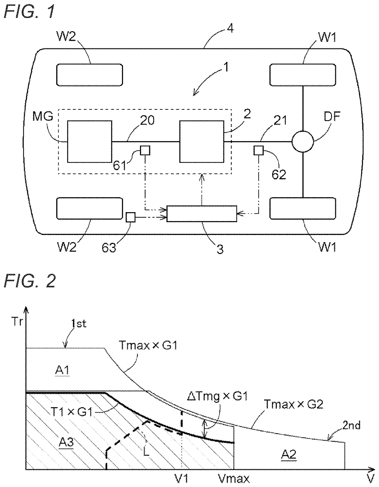
[0019]A first embodiment of a control device will be described with reference to drawings (FIGS. 1 to 3). Note that in this specification a “rotating electrical machine” is used as a concept that includes all of a motor, a generator, and a motor-generator that functions as both a motor and a generator as necessary. Note also that in this specification “drive-coupled” refers to a state in which two rotating elements are coupled together so that they can transmit drive power. This concept includes a state in which two rotating elements are coupled together such that they rotate together, and a state in which two rotating elements are coupled together via one or more power transmission members so that they can transmit drive power. Such power transmission members include various types of members (shafts, gear mechanisms, belts, chains, etc.) that transmit rotation at the same speed or at a changed speed, and may include engagement devices (friction engagement devices, mesh engagement d...

second embodiment

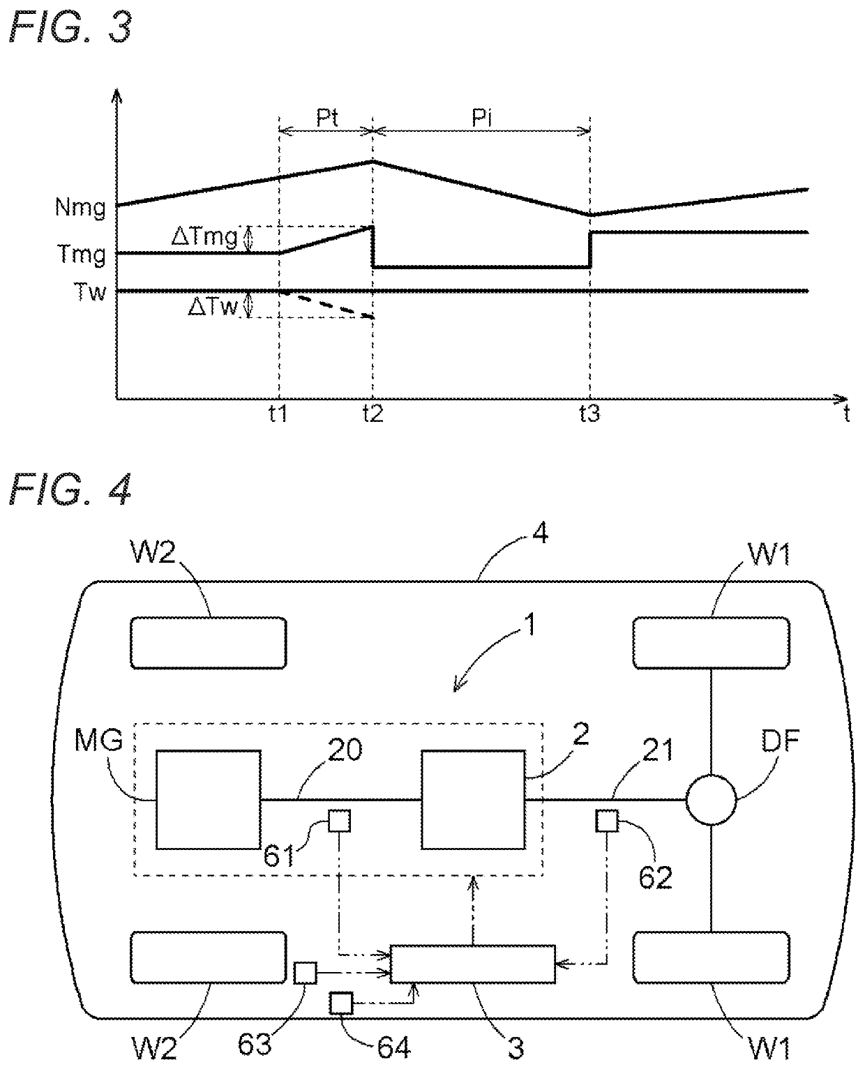
[0053]A second embodiment of a control device will be described with reference to drawings (FIGS. 4 to 9). The following mainly describes differences between the control device of the present embodiment and the control device of the first embodiment. Components that are not specifically stated are the same as those of the first embodiment, and thus are given the same reference signs and a detailed description thereof is omitted.

[0054]In the present embodiment, as shown in FIG. 4, a plurality of sensors whose detection information can be obtained by the control device 3 include a fourth sensor 64 in addition to the first sensor 61, the second sensor 62, and the third sensor 63.

[0055]The fourth sensor 64 is a sensor for detecting an operation of changing the shift speed (shift operation) by a driver of the vehicle 4, and the control device 3 detects a driver's shift operation (upshifting operation or downshifting operation) based on detection information of the fourth sensor 64. The f...


PUM


Abstract

A control device performs upshifting in a state in which an operating point of a rotating electrical machine for outputting requirement-based torque at wheel-based rotational speed falls within an operable range of the rotating electrical machine both before and after shifting a shift speed by the upshifting, and in which before shifting the shift speed, output torque from the rotating electrical machine is less than or equal to determination torque (T1), the wheel-based rotational speed being rotational speed of the rotating electrical machine based on rotational speed (V) of a wheel, the requirement-based torque being output torque from the rotating electrical machine based on required wheel transmission torque, and the determination torque (T1) being torque obtained by subtracting an amount of increased torque (ΔTmg) resulting from torque increase control from maximum torque (Tmax) that can be outputted from the rotating electrical machine at the wheel-based rotational speed.

Description

CROSS REFERENCE TO RELATED APPLICATIONS[0001]This application is a National Stage of International Application No. PCT / JP2019 / 028523 filed Jul. 19, 2019, claiming priority based on Japanese Patent Application No. 2018-139550 filed Jul. 25, 2018 and Japanese Patent Application No. 2018-139551 filed Jul. 25, 2018 the contents of which are incorporated in their entirety.TECHNICAL FIELD[0002]The present disclosure relates to a control device whose control target is a vehicle drive device having an automatic transmission provided in a power transmission path that connects a rotating electrical machine to a wheel.BACKGROUND ART[0003]An example of a control device such as that described above is described in JP 2014-47817 A (Patent Literature 1). Reference signs shown in parentheses in description of the Background Art below are those of Patent Literature 1. A control target for a control device described in Patent Literature 1 is a vehicle motor drive device (A) such as that shown in FIG....

Claims


Application Information

Patent Timeline
Patent Type & Authority Applications(United States)
IPC IPC(8): B60W30/19B60L15/20B60W10/10B60W10/08F16H61/16B60W30/20F16H59/14F16H59/70F16H61/04F16H63/50
CPCB60W30/19B60W2720/30B60W10/10B60W10/08F16H61/16B60W30/20F16H59/14F16H59/70F16H61/04F16H63/502B60L2240/48B60W2710/083B60W2710/1005B60W2520/28B60W2520/30B60W2510/083B60W2510/081B60W2530/00B60L15/2054B60L15/20F16H59/40F16H59/46F16H61/68F16H63/50Y02T10/72F16H61/0204F16H2059/148F16H61/0213F16H2061/0216Y02T10/62
Inventor WATANABE, RYOSATO, YASUYUKIKIMATA, KENTAIWASE, TAKUROOHTSUBO, JUNICHIRO
Owner AISIN CORP
Why Eureka
Try Eureka