Image forming apparatus

Inactive Publication Date: 2022-04-21
KYOCERA DOCUMENT SOLUTIONS INC
View PDF0 Cites 0 Cited by
  • Summary
  • Abstract
  • Description
  • Claims
  • Application Information

AI Technical Summary

Benefits of technology

[0009]According to the above-described configuration, it is possible, while maintaining sheet productivity, to obtain an effe

Problems solved by technology

When the sheet after being subjected to fixing is discharged, without being sufficiently cooled, to a discha

Method used


Image

  • Image forming apparatus
  • Image forming apparatus
  • Image forming apparatus

Examples


Embodiment Construction

[Diagrammatic Configuration of Image Forming Apparatus]

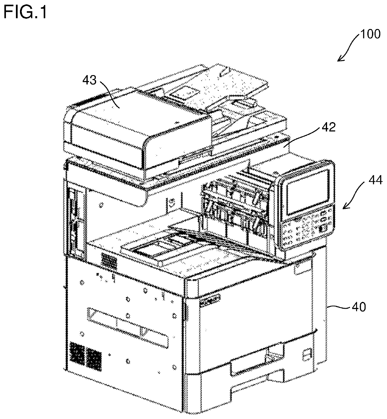
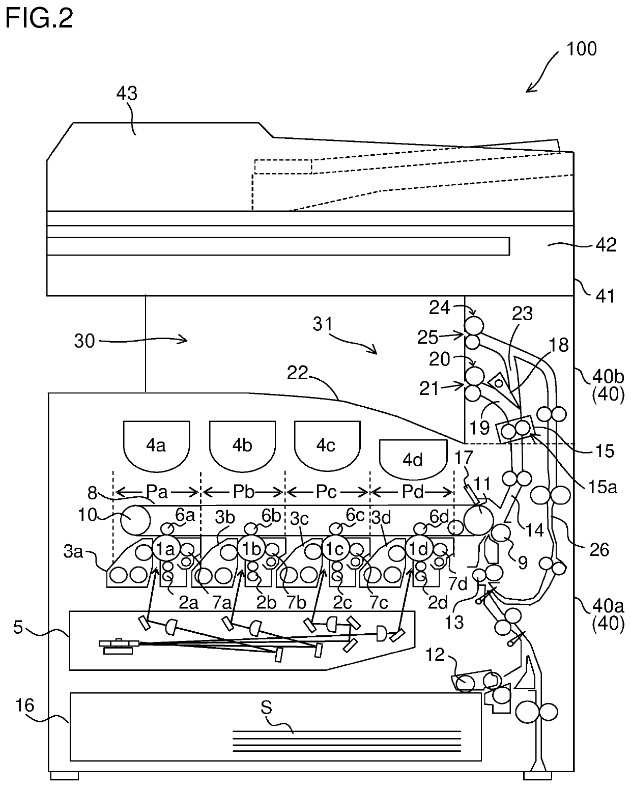
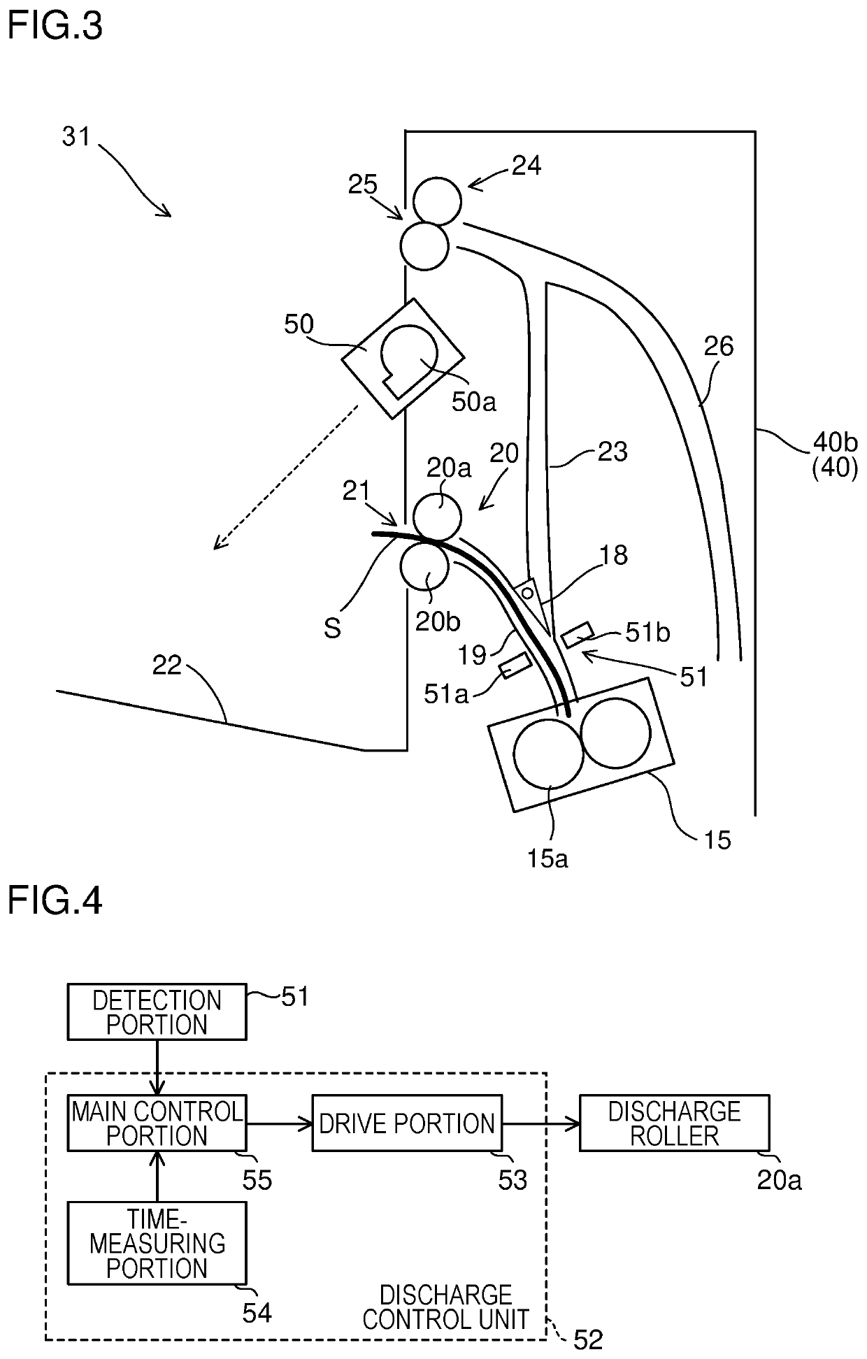
[0019]In view of the above-described problem, the present invention provides an image forming apparatus that is capable, while maintaining sheet productivity, of improving an alignment property of sheets on a discharge tray and suppressing sticking between the sheets. The following describes an embodiment of the present invention with reference to the appended drawings. FIG. 1 is a perspective view showing an external configuration of an image forming apparatus 100 according to one embodiment of the present invention, and FIG. 2 is a sectional view schematically showing a diagrammatic configuration of the image forming apparatus 100. The image forming apparatus 100 is, for example, a tandem color copy machine of an intra-body paper discharge type. The image forming apparatus 100 is composed generally of a main body housing 40 and an upper housing 41 disposed above the main body housing 40.

[0020]An image reading portion 42 is pro...


PUM


Abstract

An image forming apparatus includes a fixing device, a discharge roller pair, a detection portion, and a discharge control unit. The discharge roller pair discharges a sheet on which a toner image has been fixed in the fixing device to a discharge tray via a discharge port. The detection portion detects a rear end of the sheet being conveyed from the fixing device toward the discharge port. The discharge control unit performs control so that, within a prescribed period from a point in time of detection of the rear end of the sheet by the detection portion to when the rear end of the sheet passes through the discharge roller pair, a discharge speed of the sheet is reduced to a value lower than a reference speed, and after a lapse of the prescribed period, the discharge speed is increased back to the reference speed.

Description

TECHNICAL FIELD[0001]The present invention relates to an image forming apparatus using an electrophotographic method, such as a copy machine, a printer, a facsimile, or a multi-functional peripheral having functions of these apparatuses.BACKGROUND ART[0002]In such an image forming apparatus using the electrophotographic method, toner is applied to an electrostatic latent image formed on an image carrier such as a photosensitive drum so that a toner image is formed thereon. Further, the toner image thus formed is transferred to a sheet such as a paper sheet, and then the toner image on the sheet is fixed by a fixing device.[0003]Meanwhile, a sheet immediately after being subjected to fixing is in a heated state at a considerably high temperature. When the sheet after being subjected to fixing is discharged, without being sufficiently cooled, to a discharge tray and stacked thereon, re-fusion of toner might occur, causing stacked sheets to stick to each other. To address this issue, t...

Claims


Application Information

Patent Timeline
IPC IPC(8): G03G15/20G03G15/00
CPCG03G15/2028G03G15/6552B65H43/08
Inventor MORITA, TAKAHITOOMURA, HIROYOSHI
Owner KYOCERA DOCUMENT SOLUTIONS INC
Why Eureka
Try Eureka