
Electronic device

Pending Publication Date: 2022-04-28
GETAC TECH CORP
View PDF5 Cites 0 Cited by
  • Summary
  • Abstract
  • Description
  • Claims
  • Application Information

AI Technical Summary

Benefits of technology

The patent describes an electronic device with multiple antennas that are placed in the device's base shell and have adjustable positions and angels. This ensures that each antenna has a beam that faces a specific axis. The device also adjusts the beam directions and angles based on signal quality and strength to ensure that it is accurately pointing towards a base station and preventing signal interruption. As a result, the device provides stable connection quality and higher transmission rates with the base station.

Problems solved by technology

However, as the number of antenna elements continues to increase, the space within an electronic device is not accordingly increased.
As a result, designers are faced with numerous new tough challenges.

Method used


Image

  • Electronic device
  • Electronic device
  • Electronic device

Examples


Embodiment Construction

[0027]In some wireless communication systems (for example, millimeter wave communication systems), signals may be transmitted or received between a base station and a user device (for example, a laptop computer) by a plurality of antennas. An electronic device provided by an embodiment of the present invention is applicable to an electronic device (for example, a laptop computer) having a wireless communication function.

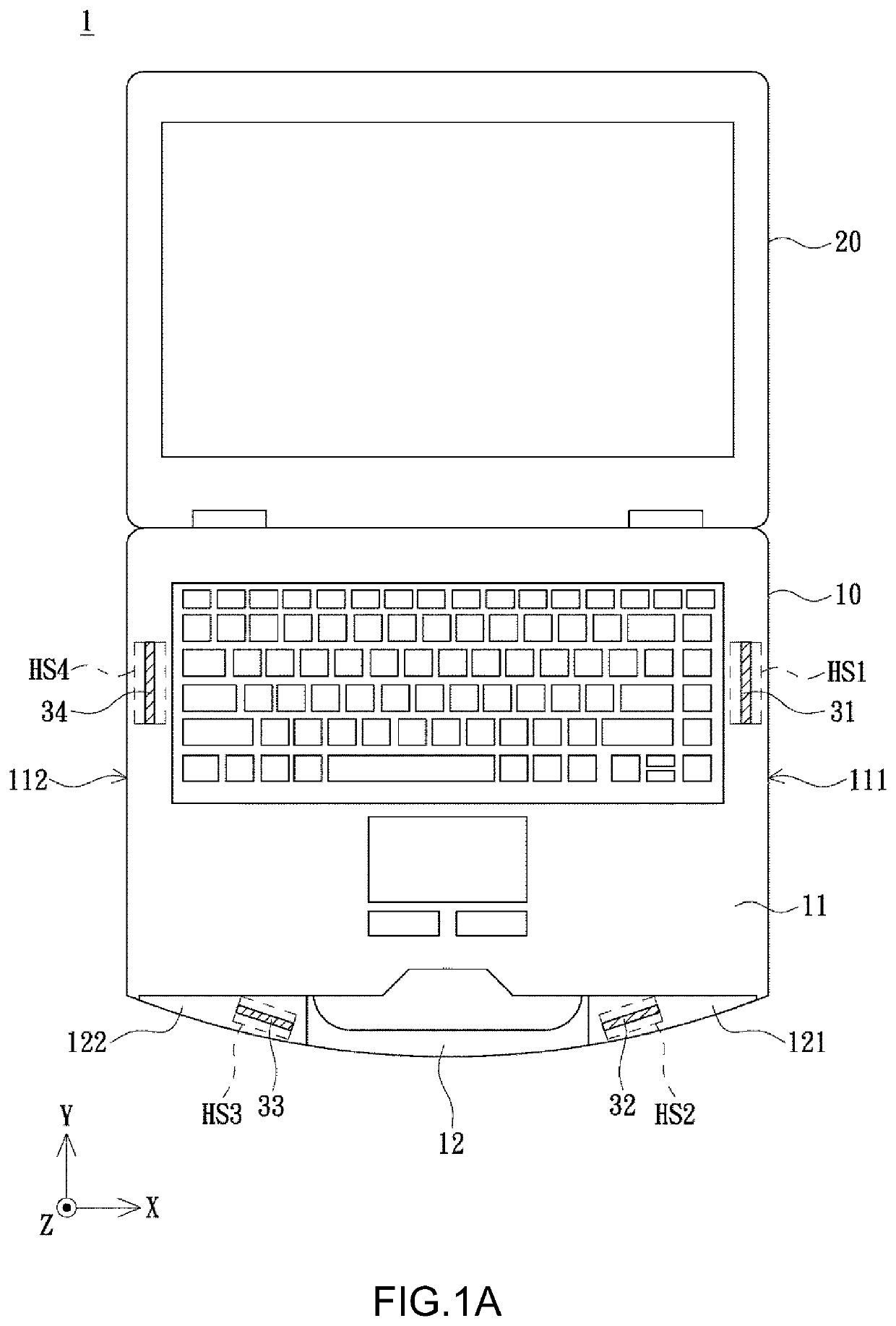
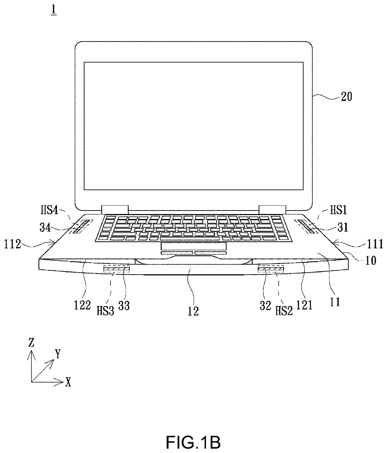
[0028]Refer to FIG. 1A and FIG. 1B. FIG. 1A shows a schematic diagram of an electronic device depicted according to an embodiment of the present invention, and FIG. 1B shows another schematic diagram of an electronic device depicted according to an embodiment of the present invention. An electronic device 1 provided according to an embodiment of the present invention includes a host device 10 and a display device 20. The host device 10 includes a base shell 11 and a handle 12, wherein the base shell 11 has a first side 111 and a second side 112, the second side 112 i...


PUM


Abstract

An electronic device provided includes a host device and a display device. The host device includes a base shell and a handle, wherein the base shell has a first accommodating space and a fourth accommodating space. The handle has a second accommodating space and a third accommodating space. The electronic device further includes a first array antenna, a second array antenna, and a third array antenna. The first array antenna, the second array antenna, and the third array antenna are respectively arranged in three of the first accommodating space, the second accommodating space, the third accommodating space, and the fourth accommodating space, wherein the first array antenna, the second array antenna, and the third array antenna respectively have a first beam, a second beam, and a third beam facing a first axis. Accordingly, the electronic device provides stable connection quality and a higher transmission rate.

Description

[0001]The application claims priority to a CN Patent Application No. 202011146695.6, filed on Oct. 23, 2020, the disclosure of which is also hereby incorporated by reference herein in its entirety.BACKGROUND OF THE INVENTIONField of the Invention[0002]The present invention relates to an electronic device, and more particularly, to an electronic device with a plurality of array antennas arranged in a base shell.Description of the Prior Art[0003]Along with the thriving development of wireless bandwidth networks and mobile communication technologies, diversified electronic products (for example, cell phones, tablet computers or laptop computers) with a wireless communication function have become popular extensively, such that the number of antenna elements is also increased with the evolving communication technologies. However, as the number of antenna elements continues to increase, the space within an electronic device is not accordingly increased. Moreover, distances between antenna...

Claims


Application Information

Patent Timeline
IPC IPC(8): H01Q3/36H01Q1/24
CPCH01Q3/36H01Q1/24H04B7/0408H01Q1/2266H01Q21/28H01Q1/22
Inventor CHENG, KUO-HENGKAO, CHIA-CHUN
Owner GETAC TECH CORP
Learn More