Method for Determining Target Spot Path

a path and target technology, applied in the field of medical technology, can solve problems such as the problem of how to improve the accuracy of the path, and achieve the effects of improving the accuracy of surgery, avoiding the occupation of space by the shooting device, and improving the accuracy of the operation

Pending Publication Date: 2022-05-05
HANGZHOU SANTAN MEDICAL TECH
View PDF0 Cites 2 Cited by
  • Summary
  • Abstract
  • Description
  • Claims
  • Application Information

AI Technical Summary

Benefits of technology

[0067]The technical solutions provided by the embodiments of the present application may have the following advantageous effects:
[0068]When the simulated two-dimensional image is matched with the two-dimensional projection image, the present application can determine the perspective coordinate information of the target spot path through the three-dimensional posture information of the virtual path, so as to assist medical staff in introducing the instrument and improve the accuracy of surgery; moreover, the locating device is separate from the shooting device in the present application, so that the shooting device can be removed after the first conversion relationship is determined, and the target spot path can be determined through the locating device, which avoids the occupation of surgical space by the shooting device and makes more room for the medical staff to perform operations.
[0069]The shooting device and the locating device in the present application are independent from each other. Locating balls on the calibration device and the locating device are used for identification and for obtaining a relative position relationship, so that the shooting device can be removed after the relative position relationship is determined. The locating device can adjust the pointing structure according to the relative position relationship and the conversion relationship between the coordinate systems so that the pointing structure points to the target spots in vivo, thereby realizing the locating of the target spots in vivo, while also avoiding occupation of the space by the shooting device.
[0070]The present application obtains the three-dimensional posture parameters of the three-dimensional partial image when the simulated two-dimensional image is matched with the two-dimensional image, thereby obtaining the perspective position information of the affected part when based on the shooting device; further, the perspective position information is converted to the projection coordinate system through the coordinate conversion relationship for projection, so that the medical staff can project the affected part to any suitable position according to needs, which is advantageous for observing the operation process at any time and realizing non-invasive real-time projection. In particular, the projection on the virtual path can provide assistance to the medical staff in insertion of the needle, which is helpful for improving the accuracy of the operation.
[0071]In the present application, physical posture parameters, which are based on the shooting device, of the surgical path in the affected part is obtained by matching the simulated two-dimensional image with the two-dimensional projection image, so that the pointing structure can be adjusted according to the physical posture parameters to sequentially point to a plurality of target spots constituting the surgical path. Based on this, a planned route on the body surface that corresponds to the surgical path can be obtained. The planned route can assist the medical staff in implanting surgical instruments and assist in path planning during the operation, which is advantageous for improving the accuracy of the operation and relieving the pain of the patient.
[0072]By matching the simulated two-dimensional image with the two-dimensional projection image, and determining path information in the two-dimensional projection image according to the projection of the virtual path in the simulated two-dimensional image in a case where it is confirmed that the simulated two-dimensional image is matched with the two-dimensional projection image, the present application enables the medical staff to intuitively learn the path information so that the medical staff is assisted in determining the current needle entry point and needle entry angle, which is advantageous for improving the accuracy of the operation and relieving the pain of the patient.

Problems solved by technology

Based on the importance of the path, how to improve the accuracy of the path has become a technical problem that needs to be solved urgently by people.

Method used


Image

  • Method for Determining Target Spot Path
  • Method for Determining Target Spot Path
  • Method for Determining Target Spot Path

Examples


first embodiment

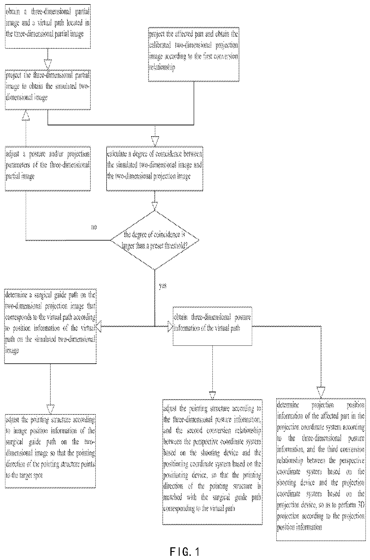
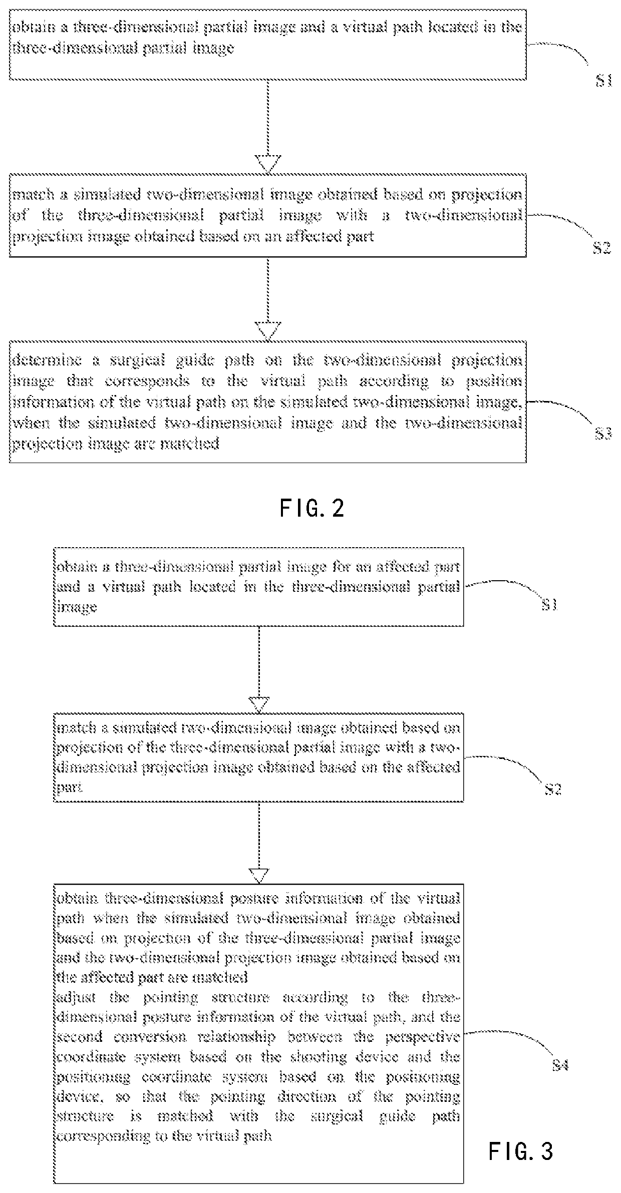
[0124]As shown in FIG. 5, the process of determining the surgical guide path on the two-dimensional projection image that corresponds to the virtual path may include the following steps.

[0125]In step 101, a three-dimensional partial image is reconstructed according to scanned information.

[0126]In step 102, a virtual path located in the three-dimensional partial image is obtained. The way of obtaining the virtual path is as described above, and will not be repeated herein.

[0127]In step 103, a spatial posture and / or projection parameters of the three-dimensional partial image are adjusted. The adjustment manner is as described above, and will not be repeated herein.

[0128]In step 104, projection is performed on the three-dimensional partial image to obtain a simulated two-dimensional image.

[0129]In step 105, a first projection area is extracted based on the simulated two-dimensional image.

[0130]In step 106, an affected part is shot to obtain a two-dimensional projection image.

[0131]In ...

second embodiment

[0158]As shown in FIG. 9, the process of the auxiliary method for determining the target spot may include the following steps.

[0159]In step 301, calibration position information O1_2d of a first preset mark point O in the calibration coordinate system XOY is obtained.

[0160]In this embodiment, the image shot by the C-arm machine can be calibrated by a preset calibration device, and the preset calibration device can be provided with a plurality of first preset mark points. The calibration coordinate system is located at any position on the preset calibration device, and each of the first preset mark points is located on the calibration device, so that the calibration position information of each of the first preset mark points is known. In this embodiment, assuming that the origin is located on an upper surface of the calibration plate, then a calibration coordinate system XOY can be established based on an extending direction of the upper surface, and calibration position information...

third embodiment

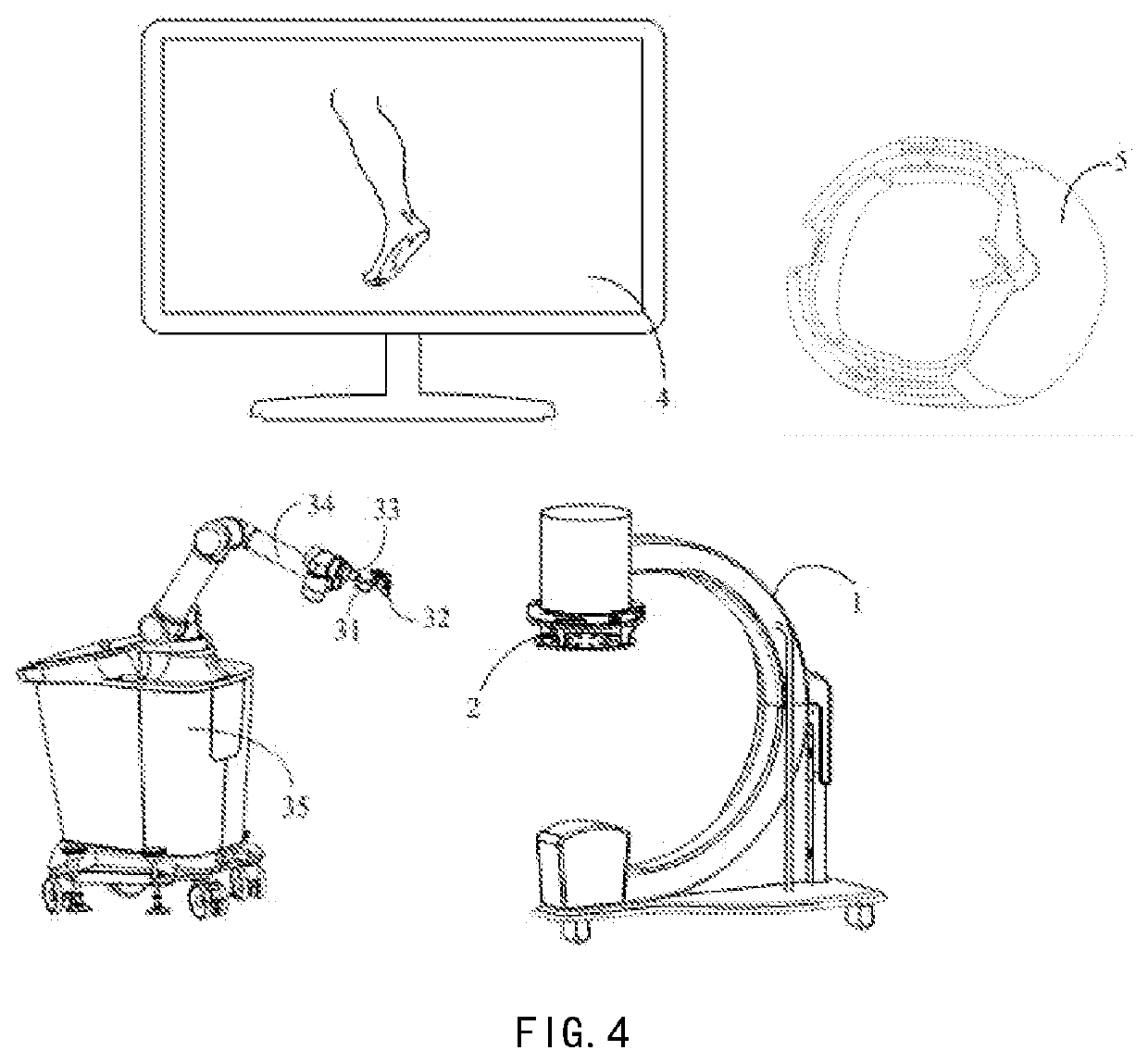
[0183]FIG. 11 is a flowchart showing a projection method according to an exemplary embodiment. It can be applied to the device shown in FIG. 4. The system for determining the target spot path may include a projection device 5, and a projection coordinate system can be established based on the projection device. As shown in FIG. 11, the following steps may be included:

[0184]In step 601, coordinates E1_3d of a fourth locating ball E based on the calibration coordinate system are obtained.

[0185]In this embodiment, the fourth locating ball E may be arranged on the calibration device, so that the coordinates E1_3d of the fourth locating ball E relative to the calibration coordinate system are known.

[0186]In step 602, coordinates E2_3d of the fourth locating ball based on the projection coordinate system is obtained by the projection device.

[0187]In step 603, the third conversion relationship T3 between the projection coordinate system and the perspective coordinate system is calculated a...


PUM


Abstract

The present disclosure relates to a method for determining a target spot path, which is applied to a determining system including a shooting device and a locating device that are separate from each other, and a calibration device connected to the shooting device, the method comprising: S1. obtaining a three-dimensional partial image for an affected part and a virtual path located in the three-dimensional partial image; S2. matching a simulated two-dimensional image obtained based on projection of the three-dimensional partial image with a two-dimensional projection image obtained based on the affected part; S3. determining a surgical guide path on the two-dimensional projection image that corresponds to the virtual path according to position information of the virtual path on the simulated two-dimensional image, when the simulated two-dimensional image and the two-dimensional projection image are matched; and / or S4.

Description

CROSS-REFERENCE TO RELATED APPLICATIONS[0001]This Application is a national stage application of PCT / CN2020 / 077846. The present application claims priorities from PCT Application No. PCT / CN2020 / 077846, filed Mar. 4, 2020, and from the following Chinese patent applications filed with the Chinese National Intellectual Property Administration on Mar. 4, 2019: CN201910161726.6, titled “Projection Method, Device and System and Readable Storage Medium”; CN201910161268.6, titled “Auxiliary Method, Device and System for Determining Target Spot Path, and Readable Storage Medium”; CN201910161263.3, titled “Method, Device and System for Determining Target Spot Path, and Readable Storage Medium”; CN201910161265.2, titled “Locating System and Target Spot Locating Method”; and CN201910161266.7, titled “Method, Device and System for Determining Surgical Path, and Readable Storage Medium”, the entire contents of which are incorporated into the present application by reference.FIELD OF THE INVENTION...

Claims


Application Information

Patent Timeline
Patent Type & Authority Applications(United States)
IPC IPC(8): A61B34/10A61B34/20G06V10/26G06V10/50G06T7/80
CPCA61B34/10A61B34/20G06V10/26A61B2034/2065G06T7/80A61B2034/107G06V10/50A61B90/37A61B2090/376A61B90/50A61B90/13A61B2090/363A61B2560/0437A61B2017/00725G06V20/647G06V10/761G06V10/24G06V2201/03
Inventor HE, BINSHEN, LIPINGXU, SHUOGUIYAN, SHIGUILI, WEIXULI, SISHENGCHEN, HANQINGTONG, RUIXU, QIFANG, HUALEISUN, WEIWEIGUO, HONGRUI
Owner HANGZHOU SANTAN MEDICAL TECH
Why Eureka
Try Eureka