Rotor of rotary electric machine and rotary electric machine

Pending Publication Date: 2022-05-05
HONDA MOTOR CO LTD
View PDF0 Cites 0 Cited by
  • Summary
  • Abstract
  • Description
  • Claims
  • Application Information

AI Technical Summary

Benefits of technology

This patent describes a way to prevent a decrease in the output torque of a rotary electric machine and to spread the stress over the rotor core. It does this by preventing a decrease in the magnetic flux in a specific part of the machine and by distributing the load from a specific part of the machine. This reduces the risk of damage to the rotor and ensures a long lifespan for the machine.

Problems solved by technology

However, if the connection rib has reduced thickness, stress concentrates on the connection rib when the rotor core receives a radially outward centrifugal load from the permanent magnet due to a centrifugal force of the permanent magnet during rotation of the rotor, the rotor core, particularly the connection rib, is likely to be deformed radially outward, and thus there is a limit to arranging the permanent magnet on the radially outer side of the rotor core and reducing thickness of the connection rib.

Method used


Image

  • Rotor of rotary electric machine and rotary electric machine
  • Rotor of rotary electric machine and rotary electric machine
  • Rotor of rotary electric machine and rotary electric machine

Examples


Embodiment Construction

[0040]Hereinafter, an embodiment of a rotor of a rotary electric machine and the rotary electric machine including the rotor according to the present disclosure will be described with reference to accompanying drawings. The drawings are viewed in directions of reference numerals.

[0041]

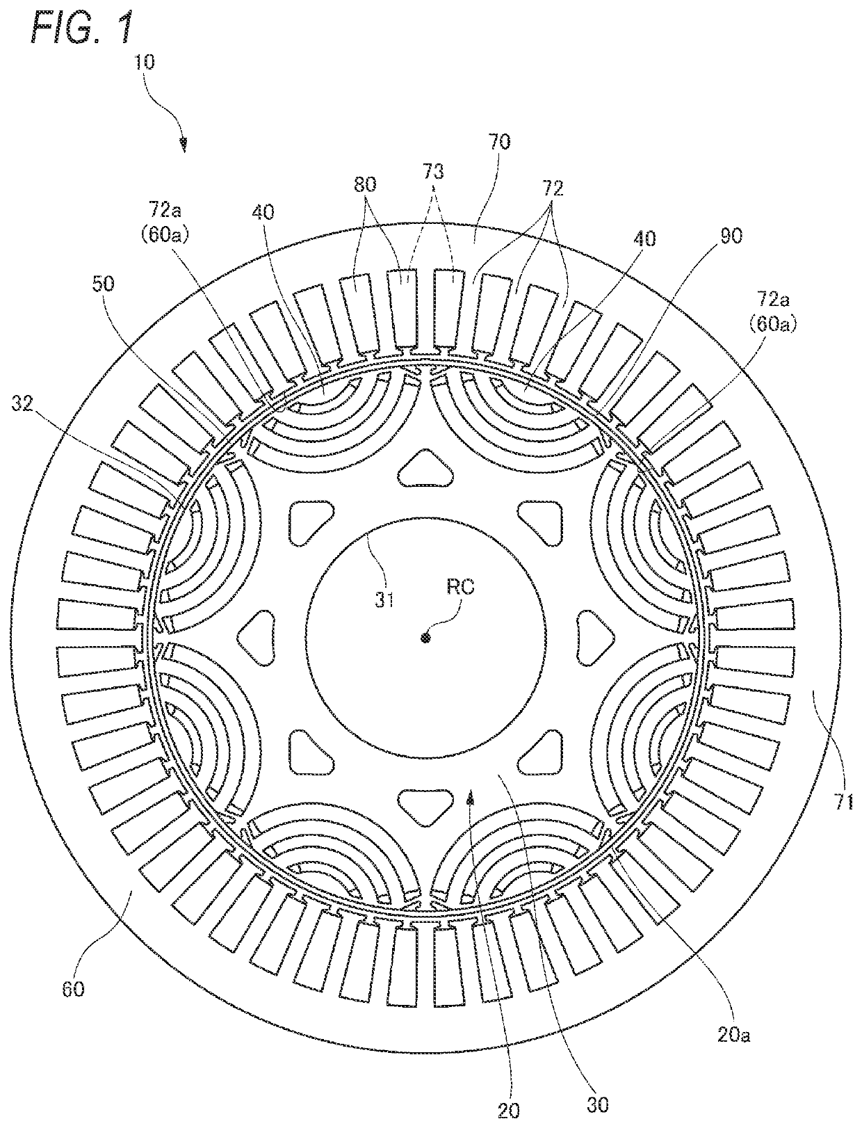
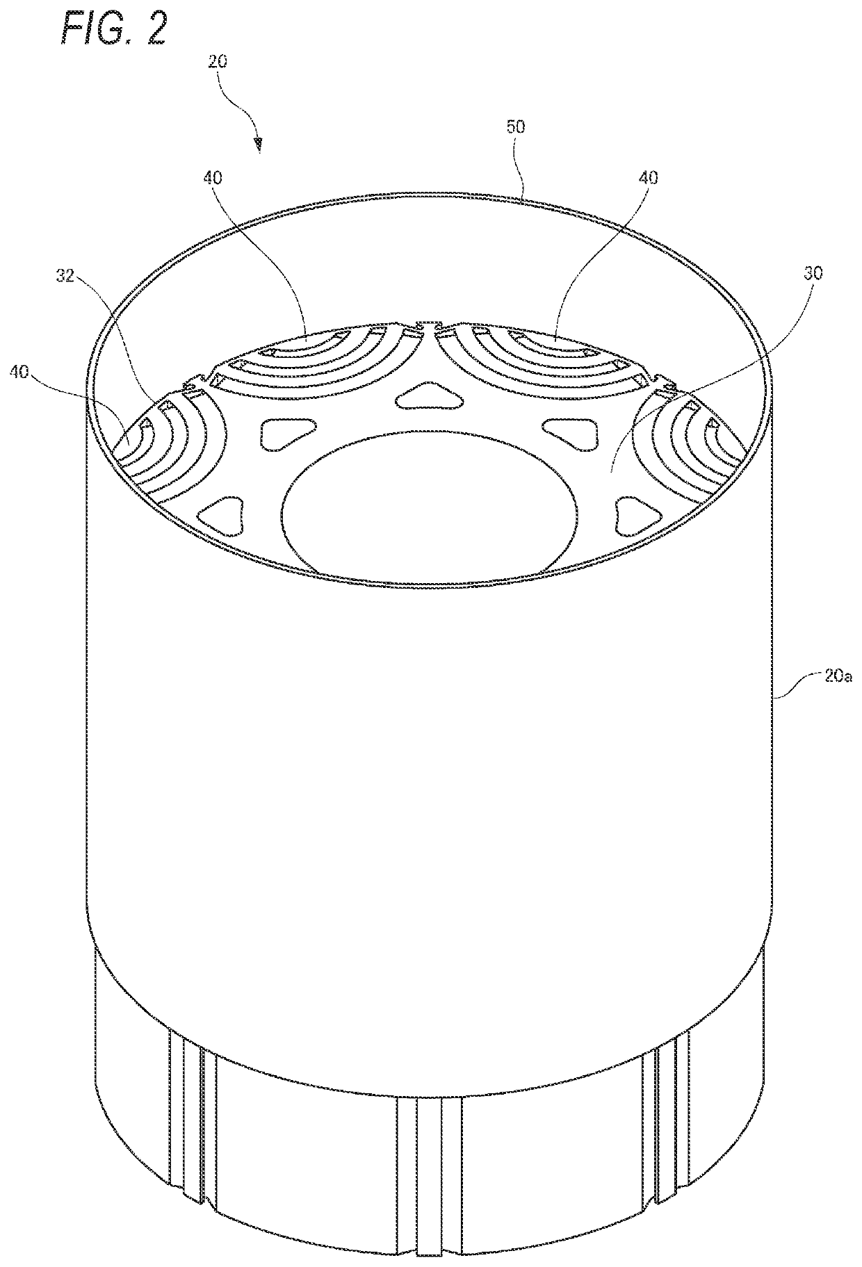
[0042]As illustrated in FIG. 1, a rotary electric machine 10 according to the present embodiment includes: a substantially annular rotor 20 which rotates with a rotation axis RC serving as a rotation axis thereof and is centered on the rotation axis RC; and a stator 60 which is arranged to surround an outer circumferential surface 20a of the rotor 20.

[0043]In the present specification and the like, unless otherwise specified, the terms “axial direction”, “radial direction”, and “circumferential direction” refer to directions based on the rotation axis RC of the rotor 20. In addition, an axially inner side refers to the side of a center of the rotary electric machine 10 in the axial direction, and an ax...


PUM


Abstract

A rotor of a rotary electric machine includes a rotor core, and a ring member. The rotor core is fastened and fixed to the ring member. The outer circumferential surface of the rotor coreincludes a groove portion which is recessed radially inward at a position overlapping the q-axis in the circumferential direction, and a protruding portion which protrudes radially outward from the groove portion. The protruding portion is provided with a pair of flange portions which protrude toward the one side and the other side in the circumferential direction from a base end portion connected to the groove portion. An outer circumferential surface of a tip end portion of the protruding portion and outer circumferential surface of the pair of flange portions have an arc shape having the same center and the same diameter as the outer circumferential surface of the rotor core.

Description

CROSS-REFERENCE TO RELATED APPLICATIONS[0001]This application is based on and claims priority under 35 USC 119 from Japanese Patent Application No. 2020-181543 filed on Oct. 29, 2020.TECHNICAL FIELD[0002]The present disclosure relates to a rotor of a rotary electric machine and a rotary electric machine mounted on an electric vehicle or the like.BACKGROUND ART[0003]In recent years, electric vehicles such as hybrid vehicles, battery-driven vehicles, and fuel cell vehicles have become widespread, and rotary electric machines such as motors and generators are mounted on such electric vehicles. As one of the rotary electric machines mounted on the electric vehicles, there has been known an interior permanent magnet (IPM) type rotary electric machine in which a plurality of permanent magnets are arranged at predetermined intervals in a circumferential direction inside a rotor core.[0004]With the widespread of electric vehicles, a rotary electric machine mounted on an electric vehicle is ...

Claims


Application Information

Patent Timeline
IPC IPC(8): H02K1/27H02K21/14
CPCH02K1/2766H02K21/14H02K1/28H02K1/14H02K3/28H02K3/522H02K2213/03
Inventor KUBOTA, YOSHIHISA
Owner HONDA MOTOR CO LTD
Why Eureka
Try Eureka