A flexible preform mould for manufacturing a preform for a wind turbine blade

a technology preforms, which is applied in the field of flexible preform moulds for manufacturing preforms for wind turbine blades, can solve the problems of large manufacturing space, time-consuming and expensive preform manufacturing, and laborious and costly preform manufacturing, so as to improve the layup process and avoid the effect of costly repairs

Pending Publication Date: 2022-05-12
LM WIND POWER AS
View PDF0 Cites 0 Cited by
  • Summary
  • Abstract
  • Description
  • Claims
  • Application Information

AI Technical Summary

Benefits of technology

[0052]When manufacturing large blades , the fibre layup in the blade mould at the root end may be challenging. Fibre material may slide down the almost vertical blade mould walls due to the almost semi-circular cross section or circumference at the root end. The sliding of fibre material during manufacturing may lead to the formation of undesired wrinkles in the shell structure, which may present zones of structural weakness within the blade and consequently expensive repairs. Thus, the relatively flat moulding surface of the preform moulds of the present invention provides for the option of forming relatively flat preforms that together cover the entire circumference of the blade half, as seen in its cross secti

Problems solved by technology

This usually requires large space for manufacturing and for storing the preforms.
In addition, the manufacturing of preforms of different shapes and sizes can be time-consuming and expensive.
Providing moulds for manufacturing preforms can be tedious and costly,

Method used


Image

  • A flexible preform mould for manufacturing a preform for a wind turbine blade
  • A flexible preform mould for manufacturing a preform for a wind turbine blade
  • A flexible preform mould for manufacturing a preform for a wind turbine blade

Examples


Embodiment Construction

[0086]The invention is explained in detail below with reference to embodiments shown in the drawings, in which

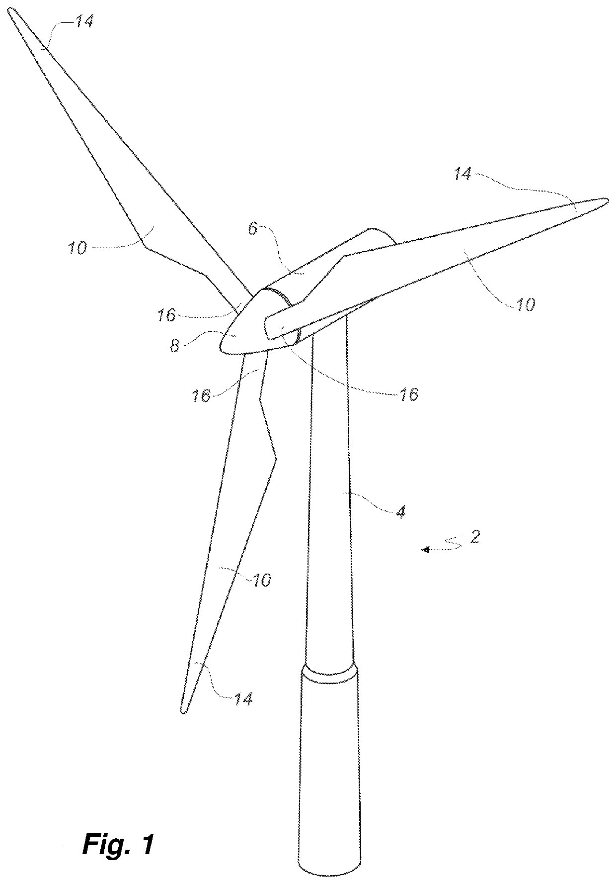
[0087]FIG. 1 shows a wind turbine,

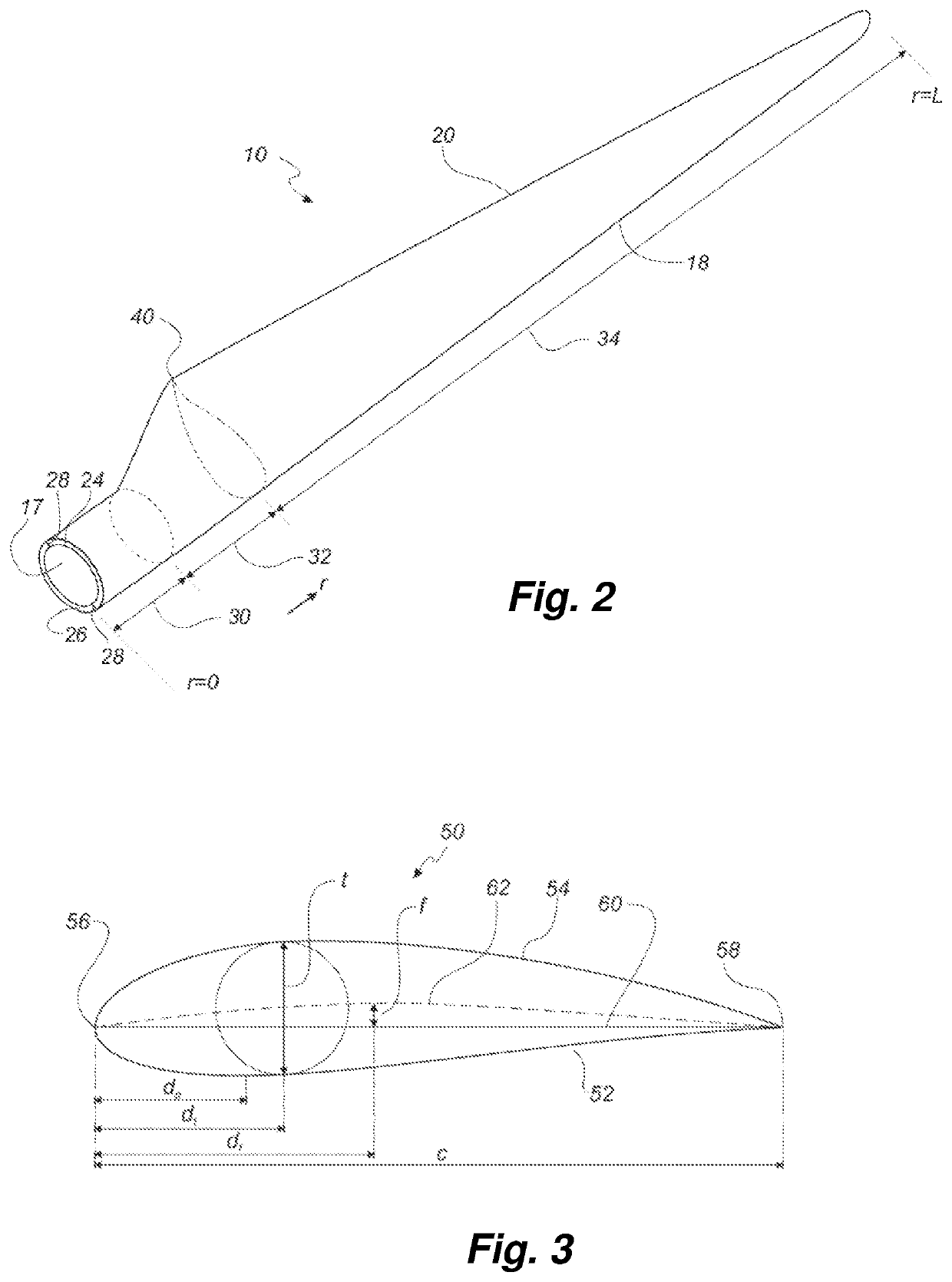
[0088]FIG. 2 shows a schematic view of a wind turbine blade,

[0089]FIG. 3 shows a schematic view of an airfoil profile through section I-I of FIG. 4,

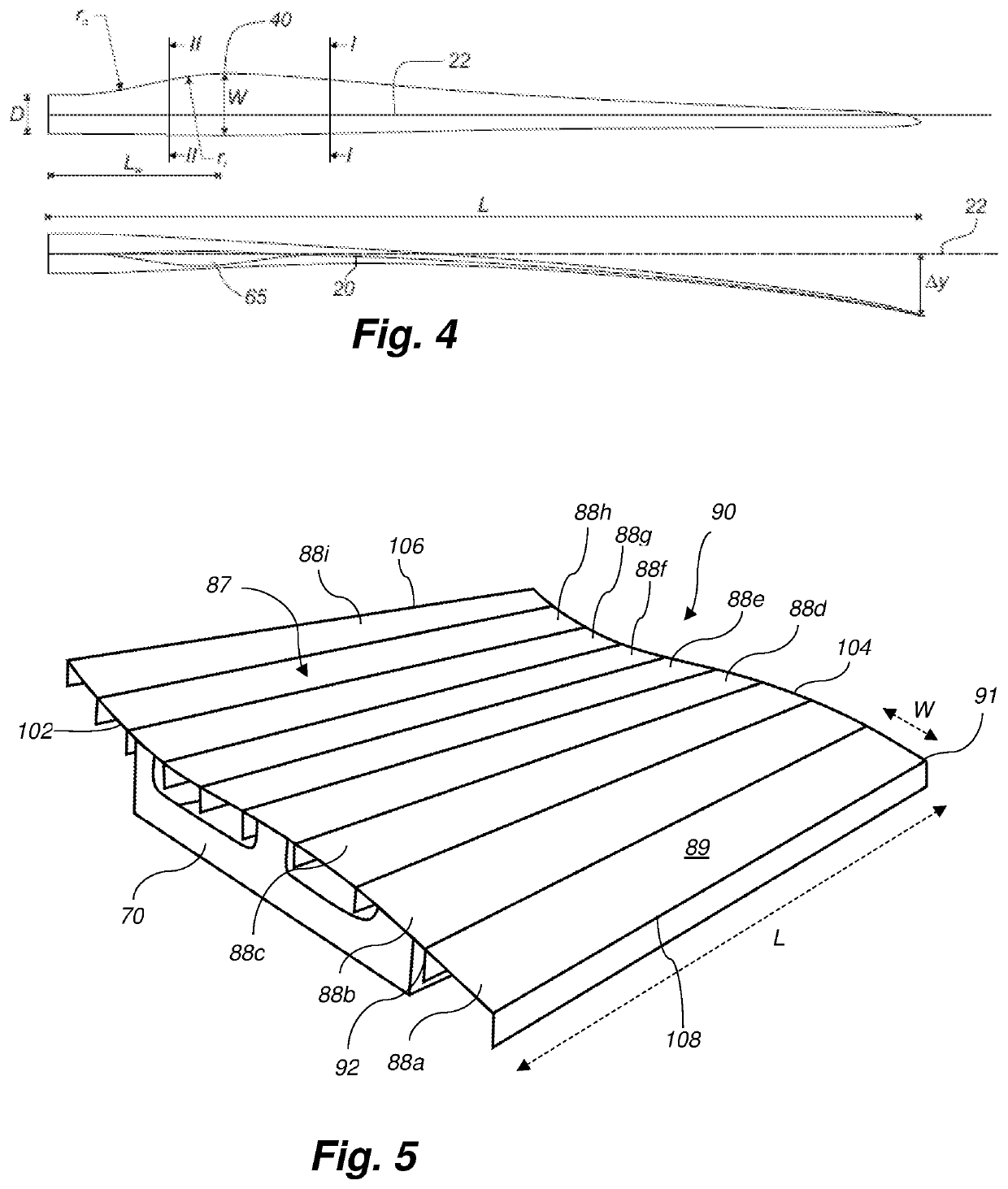
[0090]FIG. 4 shows a schematic view of the wind turbine blade, seen from above and from the side,

[0091]FIG. 5 is a perspective drawing of a preform mould according to the present invention,

[0092]FIG. 6 is a side view of a strip member according to the present invention,

[0093]FIG. 7 is a side view of plurality of strip members in a first arrangement,

[0094]FIG. 8 is a side view of plurality of strip members in a second arrangement,

[0095]FIG. 9 is a side view of plurality of strip members in a third arrangement,

[0096]FIG. 10 is an enlarged side view of part of the strip member of FIG. 6,

[0097]FIG. 11 is a perspective drawing of an arrangement of support elements for a preform mould according to the ...


PUM

PropertyMeasurementUnit
Temperatureaaaaaaaaaa

Abstract

A preform mould (90) is provided for manufacturing a preform for a wind turbine blade. The preform mould (90) comprises one or more support elements (70) and a plurality of strip members (88) comprising a top surface, a groove (64), a tongue (66), and preferably a sealing member arranged in the groove (64). The strip members (88) are arranged in juxtaposition such that the tongue (66) of a strip member (88) is releasably fixed within the groove (64) of an adjacent strip member (88).

Description

FIELD OF THE INVENTION[0001]The present invention relates to a preform mould for manufacturing a preform for a wind turbine blade, to a method of manufacturing a preform for a wind turbine blade using the preform mould, and to a method of manufacturing a wind turbine blade part using one or more preforms.BACKGROUND OF THE INVENTION[0002]Wind is an increasingly popular clean source of renewable energy with no air or water pollution. When the wind blows, wind turbine rotor blades spin clockwise, capturing energy through a main shaft connected to a gearbox and a generator for producing electricity. Rotor blades of modern wind turbines are carefully designed to maximise efficiency. Modern rotor blades may exceed 80 metres in length and 4 metres in width.[0003]Wind turbine rotor blades are typically made from a fibre-reinforced polymer material, comprising a pressure side shell half and a suction side shell half, also called blade halves. The cross-sectional profile of a typical blade in...

Claims


Application Information

Patent Timeline
IPC IPC(8): B29C33/30B29C70/44B29B11/16
CPCB29C33/302B29L2031/085B29B11/16B29C70/44Y02P70/50Y02E10/72
Inventor LEHMANN MADSEN, KRISTIAN
Owner LM WIND POWER AS
Why Eureka
Try Eureka