Centrifugal compressor with recirculation structure
a centrifugal compressor and refrigerant technology, applied in the direction of machines/engines, liquid fuel engines, lighting and heating apparatus, etc., can solve the problems of reducing compressor performance and limiting the operation range of compressors, so as to reduce compressor performance and limit the compressor operation range
- Summary
- Abstract
- Description
- Claims
- Application Information
AI Technical Summary
Benefits of technology
Problems solved by technology
Method used
Image

Examples
first embodiment
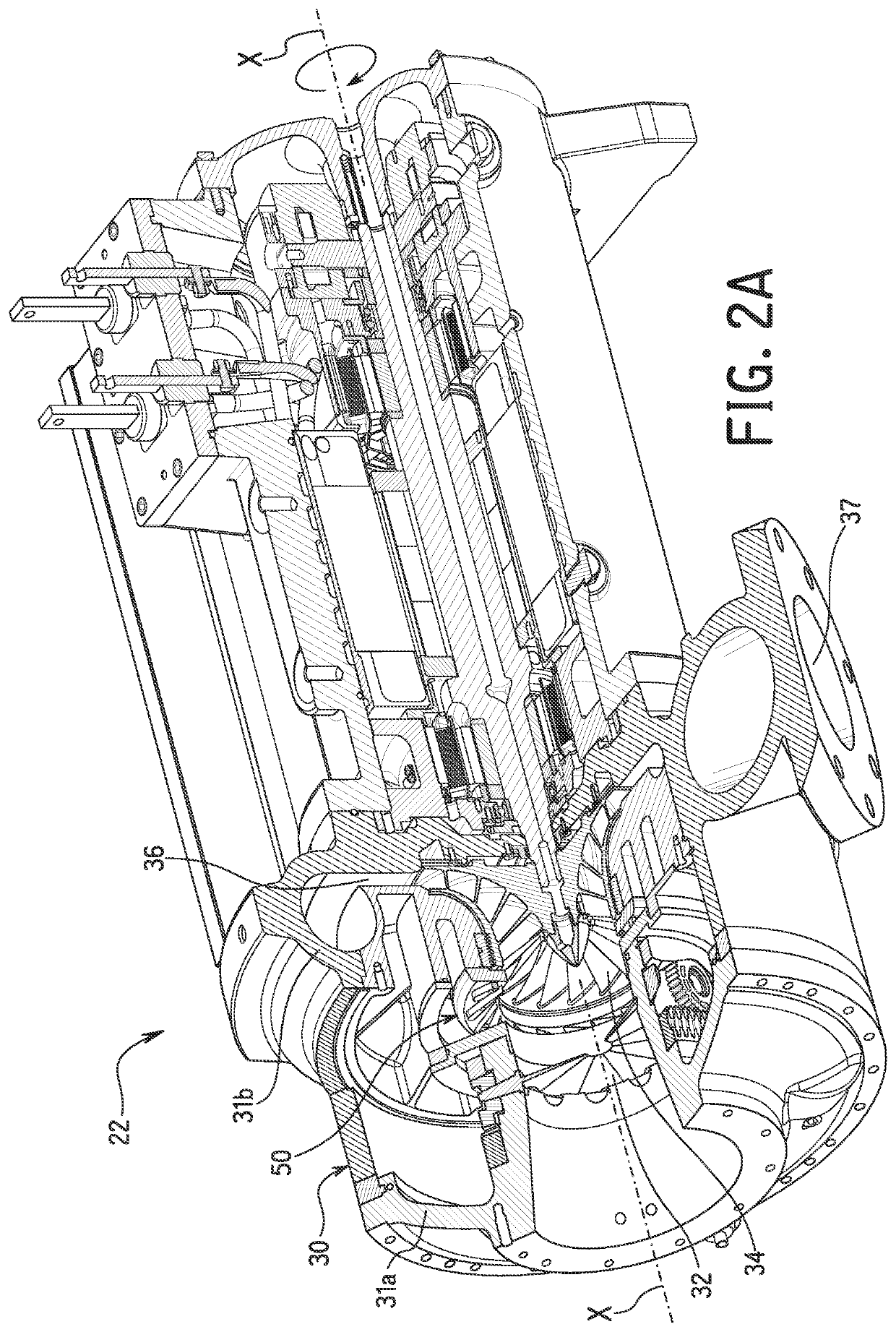
[0053]Referring now to FIGS. 2-10, the detailed structure of the recirculation structure 50 of the centrifugal compressor 22 according to the first embodiment will be explained. The casing 30 of the centrifugal compressor 22 has an inlet portion 31a and an outlet portion 31b. As best shown in FIG. 6, the recirculation structure 50 includes a recirculation path 52 and a recirculation discharge cavity 54. The recirculation path 52 of the recirculation structure 50 is disposed inside the casing 30 in this embodiment. The recirculation path 52 introduces refrigerant from the diffuser / volute 36 of the compressor 22, and the introduced refrigerant is discharged from the recirculation discharge cavity 54, as explained in more detail below.
[0054]As best understood from FIG. 6, a plurality of recirculation discharge guide vanes 56 are disposed to surround the recirculation discharge cavity 54. The recirculation discharge guide vanes 56 are circumferentially arranged with respect to a shaft r...
second embodiment
[0059]Referring to FIGS. 11A11D, the recirculation structure 50 in accordance with the second embodiment will be explained.
[0060]The recirculation structure 50 in the second embodiment further includes an interlocking plate 64 which has a similar shape to the annular plate 58 except that the interlocking plate 64 has a plurality of recesses 66 adapted to receive the plurality of recirculation discharge guide vanes 56 disposed on the annular plate 58 as illustrated in FIG. 11B. In the second embodiment, the recirculation discharge guide vanes 56 are fixedly attached to the annular plate 58 so as to fit properly in the recesses 66 of the interlocking plate 64. The interlocking plate 64 is connected to a linear actuator (not shown) so that the interlocking plate 64 can be moved axially along the direction parallel to the shaft rotation axis X of the shaft 42 of the motor 38. The linear actuator is conventional, and thus, will not be discussed and / or illustrated in detail herein. Rather...
third embodiment
[0062]Referring to FIGS. 12-15, the recirculation structure 50 in accordance with the third embodiment will be explained.
[0063]The recirculation structure 50 in the third embodiment further includes a rotating manifold plate 70 having a shape as illustrated in FIGS. 14A-14C. The plurality of recirculation discharge guide vanes 56 are attached to the annular plate 58 to be stationary in this embodiment. The plurality of recirculation discharge guide vanes 56 are disposed at a substantially same interval with each other such that channels 68 are defined between each of the plurality of recirculation discharge guide vanes 56. The plurality of recirculation discharge guide vanes 56 occupy substantially half of the flow area of the refrigerant in the radial direction as illustrated in FIGS. 15A-15C. The rotating manifold plate 70 is arranged to be rotatable about an axis which is coincident with the shaft rotation axis X of the shaft 42 of the motor 38. As the rotating manifold plate 70 ...
PUM
 Abstract
Description
Claims
Application Information
 - R&D
- Intellectual Property
- Life Sciences
- Materials
- Tech Scout
- Unparalleled Data Quality
- Higher Quality Content
- 60% Fewer Hallucinations
Browse by: Latest US Patents, China's latest patents, Technical Efficacy Thesaurus, Application Domain, Technology Topic, Popular Technical Reports.
© 2025 PatSnap. All rights reserved.Legal|Privacy policy|Modern Slavery Act Transparency Statement|Sitemap|About US| Contact US: help@patsnap.com