Method of generating residual signal, and encoder and decoder performing the method

Pending Publication Date: 2022-05-19
ELECTRONICS & TELECOMM RES INST
View PDF5 Cites 0 Cited by
  • Summary
  • Abstract
  • Description
  • Claims
  • Application Information

AI Technical Summary

Problems solved by technology

However, the existing audio coding technology may not readily restore an audio signa

Method used


Image

  • Method of generating residual signal, and encoder and decoder performing the method
  • Method of generating residual signal, and encoder and decoder performing the method
  • Method of generating residual signal, and encoder and decoder performing the method

Examples


Embodiment Construction

[0036]The following structural or functional descriptions of example embodiments described herein are merely intended for the purpose of describing the example embodiments described herein and may be implemented in various forms. However, it should be understood that these example embodiments are not construed as limited to the illustrated forms.

[0037]Various modifications may be made to the example embodiments. Here, the example embodiments are not construed as limited to the disclosure and should be understood to include all changes, equivalents, and replacements within the idea and the technical scope of the disclosure.

[0038]Although terms of “first,”“second,” and the like are used to explain various components, the components are not limited to such terms. These terms are used only to distinguish one component from another component. For example, a first component may be referred to as a second component, or similarly, the second component may be referred to as the first compone...


PUM


Abstract

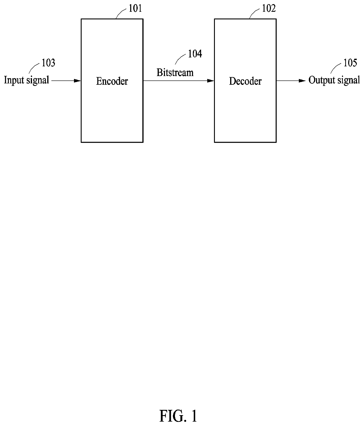
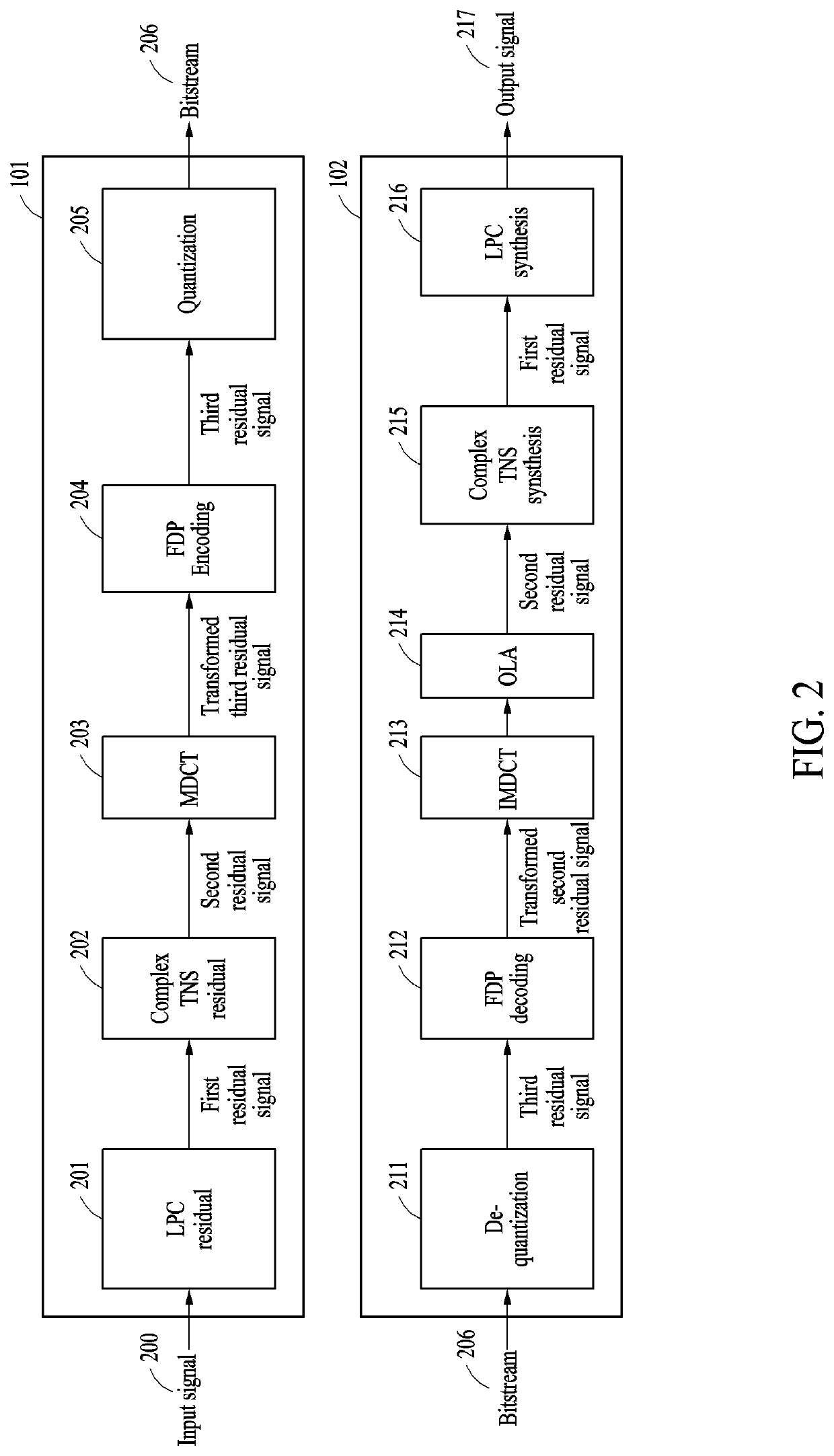
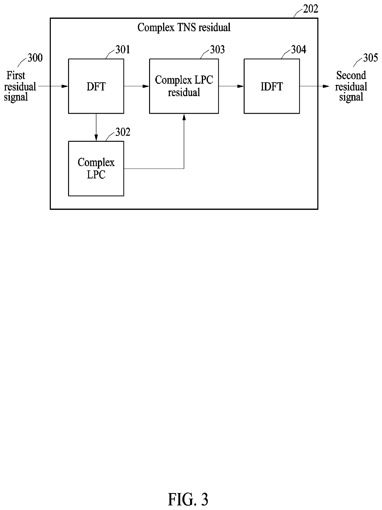
A method of generating a residual signal performed by an encoder includes identifying an input signal including an audio sample, generating a first residual signal from the input signal using linear predictive coding (LPC), generating a second residual signal having a less information amount than the first residual signal by transforming the first residual signal, transforming the second residual signal into a frequency domain, and generating a third residual signal having a less information amount than the second residual signal from the transformed second residual signal using frequency-domain prediction (FDP) coding.

Description

CROSS-REFERENCE TO RELATED APPLICATION[0001]This application claims the benefit of Korean Patent Application No. 10-2020-0153114 filed on Nov. 16, 2020, in the Korean Intellectual Property Office, the entire disclosure of which is incorporated herein by reference for all purposes.BACKGROUND1. Field of the Invention[0002]One or more example embodiments relate to a method of generating a residual signal, a method of encoding and decoding an audio signal using the method of generating a residual signal, and apparatuses performing the methods, and more particularly, to a technology for reducing an amount of information used to generate a residual signal for effective encoding.2. Description of Related Art[0003]An audio coding technology is to compress and transmit an audio signal, on which continued research is being conducted. An audio coding technology of the Moving Picture Experts Group (MPEG) has been developed to design a quantizer that is based on a human psychoacoustic model and ...

Claims


Application Information

Patent Timeline
IPC IPC(8): G10L19/13G10L19/032G10L19/06
CPCG10L19/13G10L19/06G10L19/032G10L19/08G10L25/90G10L19/087G10L19/167
Inventor BEACK, SEUNG KWONSUNG, JONGMOLEE, TAE JINLIM, WOO-TAEKJANG, INSEON
Owner ELECTRONICS & TELECOMM RES INST
Why Eureka
Try Eureka